SSZT822 january 2018 TLV9061 , TLV9062 , TLV9064
Other Parts Discussed in Post: TLV906X
Applications that require the control of a motor typically involve some type of current-sensing circuitry. Being able to sense the current through the motor allows adjustments, such as speed, to the motor’s current state if needed.
For example, in drones, each of the motors that control the propellers typically use a low-side current-sensing circuit to steer, stabilize and lift the drone through the air. In power tools like drills and reciprocating saws, low-side current sensing controls the speed of the tool based on how hard users pull the trigger. These products typically require a cost-sensitive design because they are sold in the consumer market space. In this blog post, I’ll discuss how to design a low-side current-sensing circuit for cost-sensitive applications.
One cost-effective option when designing a low-side current-sensing circuit is to use an operational amplifier (op amp) in a noninverting configuration. Figure 1 is a schematic of a typical low-side current-sensing circuit using an op amp.
 Figure 1 Low-side Current-sensing
Schematic
Figure 1 Low-side Current-sensing
SchematicEquation 1 gives the transfer function of the circuit shown in Figure 1 as:
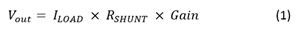
where  .
.
The design process for the low-side current-sensing circuit shown in Figure 1 breaks down into three simple steps:
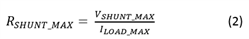
- Calculate the maximum
shunt resistance. When current from the load (ILOAD)
flows through the shunt resistor (RSHUNT), a voltage potential
(VSHUNT) develops across RSHUNT. VSHUNT
is seen as the “ground” for the system load. Therefore, I recommend keeping
VSHUNT below 100mV at the maximum load current to avoid
issues when interfacing with other systems that have a true 0V ground.
Equation 2 calculates the maximum RSHUNTvalue as:
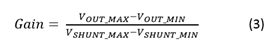
- Calculate the gain of the
amplifier. The op amp amplifies VSHUNT in order to
produce an output voltage swing of VOUT_MIN to
VOUT_MAX, where VOUT_MIN and
VOUT_MAXare the minimum and maximum output swing limits of the
amplifier, respectively. Equation 3 calculates the gain of the amplifier to
produce the desired output swing:
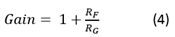
Equation 4 calculates the size of the resistors, RF and RG, in the feedback network of the amplifier in order to set the gain calculated in Equation 3:
- Choose your amplifier. In low-side current-sensing applications, the common-mode voltage can be at or below ground if the current is bidirectional; therefore, the amplifier must have an input common-mode voltage range specified at or below ground. One device with an input common-mode voltage range that extends below ground is the TLV9062, a high-performance, general purpose amplifier designed for cost-sensitive applications.
The TLV906x high-performance general-purpose amplifier family is designed for cost-sensitive low-side current-sensing applications due to its gain bandwidth (10MHz), slew rate (6.5V/µs), offset voltage (0.3mV) and input common-mode voltage range, which is specified at 100mV below the negative supply voltage. Table 1 highlights a few of the TLV906x family’s typical specifications.
| Parameter | Specification |
|---|---|
| Supply voltage range ((V+)-(V-)) | 1.8V to 5.5V |
| Quiescent current | 538µA |
| Gain bandwidth product (GBP) | 10MHz |
| Input voltage noise | 10nV/√Hz |
| Slew rate | 6.5V/µs |
| Offset voltage | 0.3mV |
| Input bias current | 0.5pA |
| Input common-mode voltage | (V-)-100mV to (V+)+100mV |
The design in Figure 2 shows the final component values for a 0A to 0.5A low-side current-sensing circuit, with component values calculated by following steps 1 through 3.
 Figure 2 0A to 0.5A Low-side
Current-sensing Schematic
Figure 2 0A to 0.5A Low-side
Current-sensing SchematicPopular applications such as drones and power tools require cost-sensitive low-side current-sensing solutions for motor control. In this post, I simplified circuit design into three simple steps: determine the maximum shunt resistor, calculate the gain of the amplifier that produces the largest output swing and choose your amplifier. In my next post, I discuss how to properly lay out a printed circuit board (PCB) for a low-side current-sensing circuit.
Additional Resources
- Start designing quickly with the 0-1A, Single-Supply, Low-Side, Current Sensing Solution.
- Watch the video, “TI Precision Labs – Op Amps: Input and Output Limitations.”