SSZT826 january 2018
In complicated power designs, metal-oxide semiconductor field-effect transistor (MOSFET) selection has a tendency to be somewhat of an afterthought. After all, it’s just a three-pin device. How complicated can it be, right? But as anyone who enjoys raw oysters will (try to) tell you, appearances can be deceiving; trying to select the correct MOSFET or “FET” can be a task more complicated than you might think.
In this 7-part series, I’ll analyze a variety of typical FET applications, from power supply to motor control, and address the various concerns and trade-offs that dictate the FET selection process. Hopefully, whether you’re a FET novice or an advanced apps engineer, you will find this series insightful the next time you have to decide on a MOSFET best suited for your system (and budget).
How to Cross-Reference a FET
A common and simple MOSFET selection process is the exercise of finding a cross-reference for a FET where the end application is generally unknown. Often times a purchasing representative will provide the engineer an exhaustive list of FETs that their client is using, with no indication as to how those devices will be used. It could even be that some FETs will be used on several different boards in multiple configurations, and they are just looking to see if you have something similar in performance to offer.
Every month, I must get dozens of requests from our field sales folks to provide TI “crosses” to our competitors’ FETs; while we try to maintain our internal cross-reference database, keeping track of every FET vendor’s entire MOSFET portfolio is a somewhat futile task. As such, the need to make crosses manually isn’t going away anytime soon. So let’s break down the process into three easy steps:
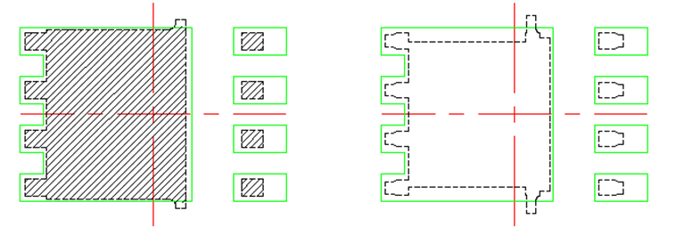
- Match the package. This may or may not be necessary, depending on whether the end application board requires footprint compatibility. If it does not, that probably opens the door to many more options, but in general, it’s a good practice to suggest something of equal or lesser footprint size. It’s important to remember that different FET vendors have different names for different packages, especially when it comes to power quad flat no-lead (PQFN)-type devices. You can always check the mechanical drawing, which is typically provided in the back of the data sheet, to confirm the footprint compatibility of two different vendors’ packages (see Figure 1).
- Match the breakdown voltage. FETs are designed to block a certain voltage, so the cross needs to have an equal or greater value breakdown voltage than the original. While selecting a FET with a higher breakdown is not technically a problem, the higher the breakdown voltage, the higher the resistance per unit area (RSP) of the silicon die, and thus the more expensive the device will have to be in order to achieve similar performance. Crossing a 60V FET for a 55V FET is probably no issue, but cross a 100V to 30V for the same performance and you will almost certainly see a major price gap.
- Match the resistance. This is the most ambiguous step in the process. It is a common misconception that resistance is the most critical parameter in all FET applications, but given that you don’t know anything about the end application, resistance is all you have to go on. It’s still a better performance metric to cross against than anything else on the data sheet, such as notoriously unreliable current ratings or gate charges, which may or may not be relevant depending on the design using the FET. When matching resistance, you can use typical or maximum values since the data sheet provides both (engineers often design to the maximum), but it is important to be consistent when doing so. A good rule of thumb is if two FETs are within ±20% resistance, they are a fairly close match.
 Figure 1 A TI Small-outline No-lead (SON) 5mm-by-6mm Package’s Recommended Printed Circuit Board (PCB) Footprint (in Green), Overlaid on Two Competitors’ Differently Named 5mm-by-6mm Surface-mount Devices (Shaded and White, Respectively)
Shows That They Are Footprint-compatible
Figure 1 A TI Small-outline No-lead (SON) 5mm-by-6mm Package’s Recommended Printed Circuit Board (PCB) Footprint (in Green), Overlaid on Two Competitors’ Differently Named 5mm-by-6mm Surface-mount Devices (Shaded and White, Respectively)
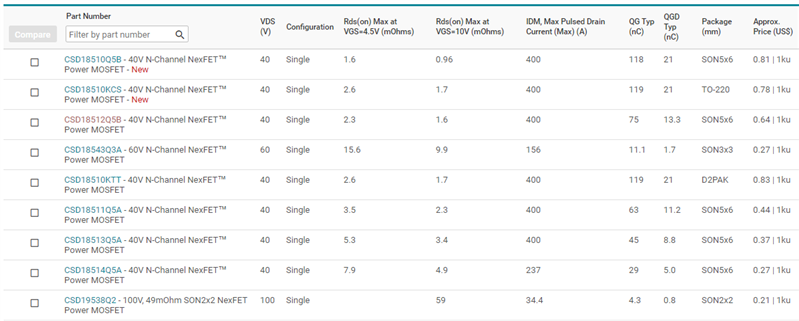
Shows That They Are Footprint-compatibleThere are many more factors to consider before placing a FET on the board, but these three checks are a good starting point. TI’s MOSFET parametric search, shown in Figure 2, makes online selection within the three parameters quick and easy.
 Figure 2 TI’s Parametric Search Makes It Easy to Select a MOSFET Based on Package, Breakdown Voltage and Resistance, as Well as Other Parameters
A last point to note is that it’s always worth it to keep an eye on cost. An older silicon generation might require a lot more silicon to achieve similar performance, and while most vendors won’t advertise the silicon generation of every device in their portfolio, they will offer relative 1,000-unit pricing that should give some you indication. If you ever come across two different devices with the same package, voltage and similar resistance but much different pricing, it is very likely that the lower-priced device is a newer solution and often a better recommendation (though future installments of this series will investigate applications where this is not necessarily the case).