SSZT871 november 2017 TPD1E1B04
In the first installment of this series, I argued for the need for discrete electrostatic discharge (ESD) protection. The different factors you need to consider when selecting an ESD protection diode for your system will be discussed.
Most circuit components do offer some kind of device-level ESD protection in compliance with charge device model (CDM) or human body model (HBM) standards. If you were to look at the data sheet spec shown in Figure 1, it would be tempting to assume that this component would be robust enough to survive ESD strikes. Perfect! Done! No discrete ESD protection required, right?
 Figure 1 Example Data Sheet with HBM
and CDM ESD Ratings
Figure 1 Example Data Sheet with HBM
and CDM ESD RatingsWell …not so fast. The CDM simulates an integrated circuit (IC) charging and discharging, while the HBM simulates a human being discharging onto the IC in a controlled ESD environment. These standards are useful in ensuring that components will survive manufacturing and assembly in factories where there are protocols to minimize ESD exposure. However, they do not accurately represent what a component will experience in an end-user scenario. I don’t know about you, but I don’t wear an ESD strap when I use my toaster in the morning.
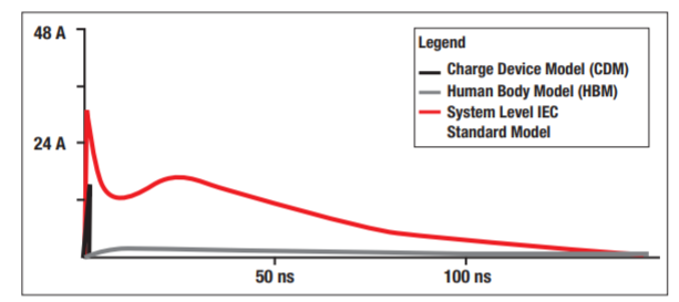
To accurately model ESD strikes in real user scenarios, the International Electrotechnical Commission (IEC) created a more rigorous standard called IEC 61000-4-2. As you can see in Figure 2, this IEC pulse has a faster rise time, a longer duration, a higher peak pulse current and significantly more energy than the CDM and HBM pulses.
 Figure 2 Comparison of Different ESD
Models
Figure 2 Comparison of Different ESD
ModelsThe IEC 61000-4-2 standard includes two different ratings for ESD that you can generally find on data sheets: contact voltage discharge (ESD directly discharged onto the device) and air-gap voltage discharge (ESD discharged onto the device through a gap of air). The IEC 61000-4-2 standard specifies four levels of voltage ratings, with level 4 being the highest (see Table 1).
| IEC 61000-4-2 Level | Contact Voltage | Air Gap Voltage |
|---|---|---|
| 1 | 2 kV | 2 kV |
| 2 | 4 kV | 4 kV |
| 3 | 6 kV | 8 kV |
| 4 | 8 kV | 15 kV |
For most applications, level 4 IEC ESD protection (8 kV contact/15 kV air gap) is sufficient. However, applications or environments where ESD strikes are expected to have stronger voltages or may occur more frequently require higher contact-voltage and air-gap voltage ratings (Table 2). TI’s TPD1E1B04, for example, has an IEC 61000-4-2 rating of 30kV/30kV.
| Source of ESD Voltage | Typical ESD Voltage at 20% Relative Humidity |
|---|---|
| Triggering a vacuum solder remover | 8 kV |
| Walking across vinyl floor | 12 kV |
| Removing plastic tape for a PC board | 12 kV |
| Removing shrink film from PC board | 12 kV |
| Spraying aerosol freezer spray | 15 kV |
| Arising from a foam cushion | 18 kV |
| Sliding plastic box on carpet | 18 kV |
| Opening a plastic bag | 20 kV |
If a device is only rated for HBM and CDM ESD, it most likely does not have enough robustness to survive continued normal operation in real-world scenarios. Therefore, when selecting ESD protection diodes to protect these devices, it is critical to select a diode that has a sufficient IEC 61000-4-2 rating to ensure that the diode itself will survive repeated exposure to ESD.
Now that you know how to compare the robustness of ESD protection diodes, in part three of this series, "ESD fundamentals, part 3: clamping voltage," I explore clamping voltage, which indicates how well a diode can protect sensitive circuitry.
Additional Resources
- View all articles in the ESD Fundamentals technical article series.
- For more information about the ISO 10605 automotive standard, see ISO 10605 Road Vehicles Test Methods for Electrical Disturbances from Electrostatic Discharge.