SSZT893 November 2017 UCC256301
Industrial power supplies are robust, highly efficient and designed to operate under a wide temperature range. Often they work without any forced cooling, which translates into the use of high-efficiency AC/DC (power factor correction [PFC]) and isolated DC/DC power stages in the system. Other key features in an industrial power supply are its ability to support short-time overload capability, hold-up time and output voltage configurability.
Industrial power supplies with output power greater than 75W need to meet International Electrotechnical Commission (IEC) 6100-3-2 class-A standards, which impose limits on the maximum current total harmonic distortion (iTHD). The front-end PFC AC/DC stage shapes the input current to the power supply so that it’s in phase with the AC mains voltage, helping increase the power factor of the system while reducing iTHD.
Popular boost topologies for implementing PFC include critical conduction mode (CrCM), continuous conduction mode (CCM) and interleaved CrCM and CCM. For universal AC input designs, the CrCM PFC is popular at power levels lower than 200W. For power levels between 200W and 500W, you can use either CCM boost or interleaved CrCM boost PFCs. At higher power levels, either CCM or interleaved CCM boost topologies are popular.
For the isolated DC/DC stage, an inductor-inductor-capacitor (LLC) converter with output synchronous rectification is very popular given its soft switching nature and ability to operate at high efficiencies.
While designing the LLC power stage for industrial power supplies, you’ll need to consider a few requirements. Two key requirements that can determine the dimensioning of the resonant tank…
Short-time Overload Feature:
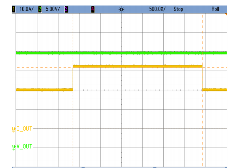
The short-time overload feature enables a system to operate under overload conditions (up to 1.5 times the rated load) for a short period of time – a few seconds. You’ll need to design the resonant tank to make sure that the system does not enter the capacitive region accidentally under this condition. Entering the capacitive region of operation can damage the primary high-voltage-side switches in the LLC converter. Typically, methods to prevent entering the capacitive region limit the LLC converter’s minimum operating frequency. But limiting the frequency does not allow the system to exploit the full safe operating region of the LLC resonant tank.
The UCC256301, with its zero current switching (ZCS) avoidance mechanism, helps prevent the system from entering the capacitive region of operation. This feature helps in the implementation of a robust LLC power stage that can protect the system under overload or short-circuit conditions and fully exploit the gain provided by the resonant tank. The short time overload functionality of the TIDA-01494 design is shown below in Figure 1.
 Figure 1 Short-time Overload Functionality of the TIDA-01494 Reference Design
Hold-up Time Requirements:
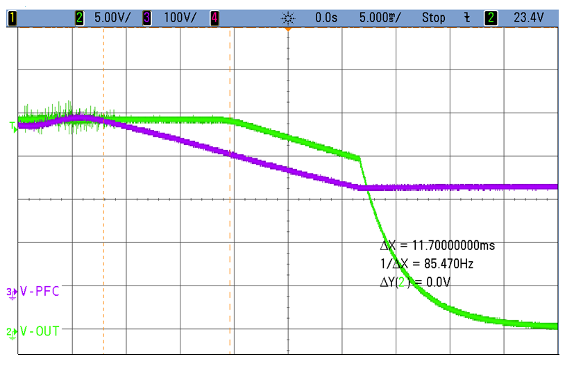
Meeting a 20ms hold-up time requires a huge bulk capacitor at the PFC output stage. One way to reduce the size of the PFC bulk capacitor is to design the LLC stage to work under wide-input-voltage conditions, such as 300V to 400V. In order to operate under wide-input-voltage conditions, the LLC converter needs to operate under a wide frequency range. The ZCS avoidance feature of the UCC256301 facilitates operation of the LLC tank up to its maximum gain frequency, thus enabling safe operations under wide input-voltage-range conditions.
Figure 2 shows the hold-up waveform on the 24V, 480W Nominal 720W Peak, >93.5% Efficient, Robust AC/DC Industrial Power Supply Reference Design. You can see the ZCS avoidance action as the bulk capacitor voltage falls below 300V. The LLC converter is operating at the maximum gain frequency of the resonant tank without slipping into capacitive region.
 Figure 2 Hold-up Waveform of the TIDA-01494 Reference Design
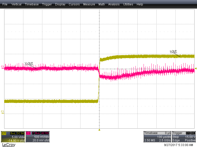
The UCC256301, with its hybrid hysteretic control resulting in fast transient response, helps minimize the output capacitor required to meet load-transient requirements. Figure 3 shows the transient response in the reference design as the load changes from 20% to 100%.
 Figure 3 The Transient Response of the TIDA-01494 Reference Design
Overall, the ZCS avoidance feature, three-level overcurrent sensing and adaptive dead-time optimization features in the UCC256301 help in the implementation of a robust, high-efficiency LLC power stage for industrial power supplies.
Additional Resources
- Gain top-notch efficiency for your desktop power-supply unit (PSU).
- Read up on how the UCC256301 can improve the power supply for your desktop PSU.
- Integrate bidirectional power flow into your uninterruptible power supply (UPS) design.