Voltage-mode Control vs. Current-mode Control
The advantages and disadvantages of voltage-mode control (VMC) vs. current mode control (CMC) are popular discussion topics. VMC has a couple of advantages over CMC because with CMC, high di/dt cycle-by-cycle
current information is injected into the feedback loop to generate a ramp voltage presented to the pulse-width modulation (PWM) comparator; this signal is compared to the error voltage. VMC generates its ramp internally and, as a result, is
less prone to noise and duty-cycle jitter.
The need to feed the cycle-by-cycle current into the feedback loop to generate a ramp requires filtering of the current information, a process known as leading-edge blanking. Leading-edge blanking affects the
minimum controllable on-time and is specified in data sheets as Ton min. The Ton min (max) is a specification often scrutinized in high step-down ratio designs because it is the minimum controllable on-time that the converter power stage
must exceed. VMC typically enables very small duty-cycle control without the impact of relatively large leading-edge blanking times.
Current Imbalances
So, addressing the original question, “Can you tie the outputs of two voltage-mode buck controllers together?,” one of the two phases will likely hit a current limit as the output of one phase sources current into
the other given the different voltage setpoints of each phase. Even if the output setpoints were not dissimilar, the phases would be unlikely to share evenly, and the imbalance would cause one of the two phases to deliver more current than
the other and one phase to get hotter than the other. In order to get the phases to share evenly, you must first measure the current.
DCR Current Sensing
Direct current resistance (DCR) sensing is a method of measuring the current in each phase that does not add additional losses or costs. Using a resistor capacitor (RC) across the inductor, as shown in Figure 1, the Cs voltage sensed across C1 is proportional to the voltage sensed across the LDCR of the inductor winding. The sensed voltage
is also proportional to the output current.
Current Sharing
Figure 2 shows the current-sharing circuit of a two-phase VMC synchronous buck controller. The difference amplifier
ensures that the voltages at VCsmstr and VCsslv are equal. For example, should the current in the master phase be greater than the slave phase, the voltage at the negative input of the amplifier will cause the output of the amplifier (Vinj)
to fall. A falling voltage at the injection resistor (Rinj) will result in an increase of the slave phase voltage. Increased current in the slave phase will decrease the current in the master phase. I recommend selecting Rin and Rfb such
that if both phases are well-matched and even, the voltage presented at the output of the amplifier (Vinj) is equal to the reference voltage of the controller and no current sources or sinks at the feedback node.
The current-sharing circuit does not account for mismatching the LDCRs of the two phases. If there is a mismatch in initial LDCR accuracy, there will be a mismatch in current between the phases. This mismatch will
self-balance to some degree, however. The current in the lower LDCR phase will be higher, and as a result of higher temperatures, the LDCR of the offending phase will increase and adjust the sharing in the right direction. Should you
require superior matching, you can use current-sense resistors instead of DCR sensing.
Current-sense Amplifier
Example
Looking
again at Figure 2, consider a dual-channel 12V output where the output currents
between the two phases are balanced at 10A each and LDCR is 12mΩ.
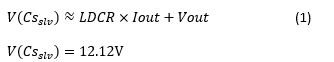
Assume that
the voltages across C1 and C2 are equal to the current multiplied by the LDCR of
each channel, respectively. See Equation 1:
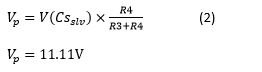
Equation 2 expresses the voltage at
the positive input to the amplifier as:
Equation 3 assumes an ideal op amp
where the voltage on its inputs are equal:
Equation 4 expresses the current
flowing through Rfb as:
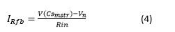
where underbalanced loads
V(Csslv) = V(Cmstr) and
IRfb = 20.2μA.
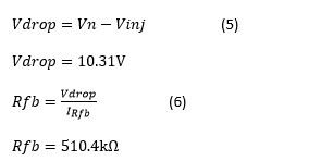
In order to have no current presented
to the feedback node under balanced conditions, the output of the amplifier must be
0.8V, which happens to be the reference voltage of the TI LM5145 buck controller. So
Equations 5 and 6 are:
Should there be an imbalance between
the phases, the output voltage will adjust above or below the 0.8V feedback voltage.
If Vout is less than the feedback voltage – say 0.7V (due to a greater amount of
current flowing in the master than the slave) – the amplifier will sink current from
the feedback node and the output voltage of the slave will adjust above the setpoint
of the feedback resistors according to Equation 7:
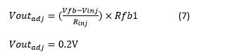
The output voltage of the slave will
increase from 12V to 12.2V, rebalancing the currents in each phase.
The current-sense amplifier requires
high-frequency attenuation; a capacitor is placed in parallel with the feedback
resistor, Rfb.
Figure 3 shows the actual design of the current-sense amplifier using the
nearest preferred values.
Putting It All Together – the LM5145 Controller in an Interleaved Buck Application
Figure 4 and Figure 5 show two LM5145 voltage-mode synchronous buck controllers configured in an interleaved
application with current balancing. As I discussed, a difference amplifier that senses the voltage drop across LDCR achieves current balancing. Some of the features of the LM5145 enable easy implementation of a two-phase interleaved buck.
The LM5145 implements diode emulation at startup and ensures that currents in one phase do not sink into the other. In the event of any current imbalance between phases, the current-sense amplifier will adjust the slave voltage above or
below its setpoint to ensure evenly loaded phases.
Another benefit of the LM5145 is the soft start and tracking input pin. Soft start slows the startup time and minimizes current mismatch during startup. In addition to soft start, you can use the tracking feature as
an option to precisely sequence the startup and settling times between the two phases. Another beneficial feature of the LM5145 is the sync in and sync out feature. Sync in ensures that the two phases are synchronized. Sync out ensures a
180-degree phase shift of the clocks, resulting in a root-mean-square (RMS) ripple-current cancellation of the input currents to the buck stages and significantly reducing the required RMS ripple-current rating of the input capacitors.
Results
Figure 6 shows measured results of the example discussed above.
Figure 7 shows the measured current sharing accuracy between two phases.
Figure 8 shows the switch node and inductor current of each phase in steady state conditions.
Figure 9 shows the dynamic performance during a load step showing how the inductor current shares between the phases during this transient
condition.
Conclusion
This blog describes how to design with the LM5145 synchronous buck controller in a dual-phase application where higher currents and higher efficiencies are required. The use of voltage-mode controllers with specific
features such as pre-bias start up (diode emulation) and SYNC IN/OUT features make for a relatively simple implementation. VMC has the advantage over CMC with jitter free, high-current performance and the ability to convert voltages with
higher step-down ratios. This implementation featuring the LM5145 does not add extra complexity, cost, or power loss compared to solutions using current-mode control. For further information on the power stage of the buck converter,
please see the application information in the LM5145 datasheet.
 Figure 1 DCR Current Sensing
 Figure 2 Current Sharing withDCR
Current Sensing
Figure 2 Current Sharing withDCR
Current Sensing Figure 3 Current-sense Amplifier
Design
Figure 3 Current-sense Amplifier
Design Figure 4 LM5145 Master Phase
 Figure 5 LM5145 and Current-sense Amplifier Slave Phase
 Figure 6 Curve Showing Peak Efficiency of Almost 97% at 24Vin, 12Vout at 11A
 Figure 7 Curve Showing Current Sharing: Master at -2.5% and Slave at +2.6% of Target
") Figure 8 Steady State Performance: 48V in Vswitch and Inductor Current at 20A Load (Channel 1 = Vswitch Master, Channel 2 = Vswitch Slave, Channel 3 = Inductor Current Master, Channel 4 = Inductor Current Slave)
Figure 8 Steady State Performance: 48V in Vswitch and Inductor Current at 20A Load (Channel 1 = Vswitch Master, Channel 2 = Vswitch Slave, Channel 3 = Inductor Current Master, Channel 4 = Inductor Current Slave) (Channel 2 = Vout, Channel 3 = Inductor Current Master, Channel 4 = Inductor Current Slave), Vout Perturbation = 100mV") Figure 9 Dynamic Performance: 48Vin Transient Response from 5A to 15A (1A/µs) (Channel 2 = Vout, Channel 3 = Inductor Current Master, Channel 4 = Inductor Current Slave), Vout Perturbation = 100mV
Figure 9 Dynamic Performance: 48Vin Transient Response from 5A to 15A (1A/µs) (Channel 2 = Vout, Channel 3 = Inductor Current Master, Channel 4 = Inductor Current Slave), Vout Perturbation = 100mV