SSZT957 september 2017 BQ25600 , BQ25601 , BQ25606

As battery technology enables smaller size and higher capacity, you’ll find battery-powered devices not only in consumer products but also industrial systems. As a designer, one of the most important questions to consider is the control method for the charging system. Should you use a microprocessor-controlled charger or a stand-alone charger?
The two most popular control methodologies are:
- Inter-Integrated Circuit (I2C)-controlled. The I2C bus is a very popular and powerful bus used for communication between a host device (or multiple host devices) and a single auxiliary device (or multiple auxiliary devices). A microcontroller, known as the host device, is necessary in order to communicate with auxiliary devices, including the charger. It’s possible for the host device to modify tens of charger system parameters via I2C on the fly. Charger status as well as fault conditions can be reported back to the host device.
- Stand-alone. The charger functions independently without any software or host control. Fixed resistors on the board determine adjustable settings like charge current and voltage limit.
Table 1 lists what you should consider when determining the control method for a charger system.
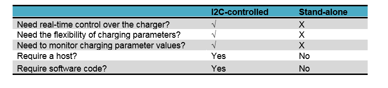
|
For industrial systems, the two most popular types of charger designs are:
- Charging the industrial battery packs inside devices (such as scanners, commercial/police radios and inventory management) via USB. This type of design usually has a built-in microcontroller to support full system functions. An I2C-controlled charger can precisely control the battery charging with the microcontroller.
- Removing the industrial battery packs from the device and charging them in a cradle with dedicated 9V or 12V adapters. Because the charging cradle is generally simple and cheaper without any microcontroller, you can use a stand-alone charger to charge the battery autonomously.
Figure 1 shows an I2C-controlled charger, where a host (microcontroller) represents the I2C host device and the charger is considered one of the auxiliary devices. The system requires both hardware and software to operate. The host can not only adjust the basic charger voltage and current parameters over wide ranges, but also program safety-timer length, thermal regulation temperature, battery temperature profile settings, boost-mode output voltage and current limit. If any fault occurs, the host will be informed with the fault-condition information. Some advanced chargers may even feed actual charger operating conditions back to the host so that the host can analyze the data and take any necessary action.
 Figure 1 Example I2C-controlled
Charger
Figure 1 Example I2C-controlled
ChargerFigure 2 shows a typical stand-alone charger. The ICHG pin resistor sets the charge current. The VSET pin voltage controls the charge voltage limit. The ILIM pin resistor determines the input current limit. Once you build the board, there’s no easy and quick way to modify the parameter settings. The STAT pin will blink to indicate fault conditions, but you will have to spend time debugging exactly what is going wrong.
 Figure 2 Example Stand-alone
Charger
Figure 2 Example Stand-alone
ChargerThe control method for a charging system depends on the charging structure and system complexity. Review the overall system carefully to make the right decisions and select successful products.
Additional Resources
- Learn more about the bq25601, bq25606 and bq25600 battery chargers from TI.
- Watch the TI training, “Understanding Battery Charging IC Specifications – Part 1.”
- Download the application report, “Understanding the I2C Bus.”