SSZT984 august 2017
My parents have an SUV that they share between them. When I go home, I might also use their car to visit old friends or run errands. When all three of us are using the same car, we each have to adjust the driver’s seat height, the distance from the steering wheel and the pedals, the steering wheel height, the angle of the chair back, and the angle of the rearview and side mirrors.
Many high-end luxury automobiles have full-featured memory seats and mirrors, where drivers create their own seat “profile” with their preferred angle and height adjustments. With this feature, my parents could save time by not having to readjust the seat and mirrors.

As my colleague Clark Kinnaird discussed in his blog post, “Putting innovation in the driver’s seat,” small brushed DC motors are controlling more and more axes of seat adjustment. Existing technology to measure these seats uses magnetic Hall-Effect sensors attached to the body of the DC motor. Magnetic poles rotate in the motor shaft and provide a field for sensor capture. Multiple sensors can measure the speed and total number of motor rotations and subrotations. The number of motor rotations can be inferred and directly translated into the total distance moved by the seat for that particular axis and saved on the memory seat control module’s microprocessor.
Measuring Position
Positional memory and motor speed are not only popular for car seats. Many small-motor automotive applications – including power windows, sliding doors and lift gates – can use information about the speed of the motor to determine stall conditions for pinch detection and optimize motor speed for efficiency with pulse-width modulation (PWM) control. Side mirrors can adjust based on different user conditions, such as changing angles to a set position to give drivers a better view when backing the car into a parking spot. Small motors are everywhere in automobiles, and a simple positional memory solution provides a wide array of convenient features.
Using Motor Current Ripple to Measure Position
Over the years, research has shown methods for capturing brushed DC motor speed and rotational position by measuring the total current flowing through the motor and counting the current ripples generated by the motor’s back-electromotive force (back-EMF). This back-EMF is proportional to the motor speed and generated by the induction of magnetic energy onto the motor commutator poles. The DC motor armature voltage and sinusoidal back-EMF cause the total current flowing through the motor to have a sinusoidal waveform.
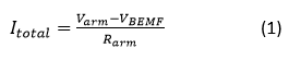
where Varm and Rarm are the voltage applied to the motor armature and the resistive load seen on the armature.
Equation 2 expands VBEMF to be represented by the frequency of the motor as:

where Ke is a motor-specific machine constant and ωr is the rotor speed.
Back-EMF will be applied to every coiled commutator pole, and every shifting of a coil within the magnetic field causes the wire to conduct and create a ripple.
As the motor is turning, the motor brushes cause a short between adjacent commutator poles. This short lowers the effective armature resistance, increasing the total current flow, as seen in Figure 1. Every commutator pole subrotation will cause this effect and add to the current ripple.
 Figure 1 Impedance Changes That Occur
Due to Motor Rotation
Figure 1 Impedance Changes That Occur
Due to Motor RotationEffective Ripple Counting
Now that you understand where motor ripple comes from, you must come up with an effective way to actually measure it. Unfortunately, it’s not as simple as just using a comparator to translate the periodic ripple signal into a general-purpose input/output (GPIO) trigger for a microcontroller. Besides the AC component signal that you need to measure, there is a widely varying common-mode DC component that makes signal biasing and comparator threshold configuration difficult.
In other applications with biasing issues, you could remedy this with a simple DC decoupling capacitor in the signal path. With correct filtering, you can remove the DC point from the output of a current-sense amplifier, while a simple resistor divider can reconfigure the bias point for optimal signal swing for the comparator stage.
For a ripple counter application, there is another issue at hand. Upon motor startup, there is a very large current spike due to the initial energy needed to fight friction and the momentum necessary to get the motor turning. Motor ripples are typically around 100 to 1000Hz, so the size of the decoupling RC filter becomes fairly large to block DC and pass the ripple signal. With the necessary RC filter size, the time constant also increases. The current spike transient is fast and large enough to not look like a DC signal for a DC-blocking capacitor.
Creative circuitry has led to the development of an innovative way to measure motor ripples while also avoiding complexity in digital signal processing. Figure 2 shows how to effectively translate the initial current measurement with the large transient spike (yellow) into a very easily measured signal for a microcontroller (purple). More details on how to achieve this can be found in the Brushed-Motor Ripple Counter Reference Design.
 into Countable Signal (Purple)") Figure 2 Translating Motor Current
Ripple (Yellow) into Countable Signal (Purple)
Figure 2 Translating Motor Current
Ripple (Yellow) into Countable Signal (Purple)Ripple counting provides a new approach for existing technologies to provide a more comfortable and convenient driving experience. As memory seats continue to expand beyond luxury vehicles, I can see my family using a car with these much-appreciated memory features. Concepts like DC motor ripple counting will help us get there.
Additional Resources
- Check out these reference designs:
- Automotive Brushed-Motor Ripple Counter Reference Design for Sensorless Position Measurement.
- Small Footprint Sunroof Motor Module Reference Design.