SSZTA00 august 2017 UCC21220 , UCC21520 , UCC28700 , UCC28704 , UCC28910 , UCC28911

Like most people on a wicked hot sunny day, all I can think about is how to beat the heat, which more often than not involves hiding in an air-conditioned room in my home. Later – on almost always a cooler day, with open windows – I’ll receive the electric bill and ask myself whether that temporary comfort was really worth it.
The air conditioner can only achieve a pyrrhic victory against the sun and its heat. As an engineer, I took this as a problem that needed solving. My solution is a simple one: if you can’t beat ’em, join ’em. Rather than consume large amounts of expensive utility electricity, it would be better if solar panels on the roof powered the air conditioner. Luckily for me I am not the first to think of this, and with costs of solar power nearly on parity with traditional energy sources, this goal is starting to become a reality for everyone.
While a lot of attention goes to the photovoltaic panel itself, the rest of the solar power ecosystem needs to advance as well. The power electronics are but one critical aspect. Since photovoltaic panels generate a DC voltage but the electricity transmission and distribution system is in AC, a power inverter is required.
To meet the cost goals of solar power systems, the U.S. Department of Energy came up with the following specifications as part of the Sunshot Initiative:
- Conversion efficiency >98%
- Service life >25 years
- Power density >100W/in3
- System cost <$0.10/W (utility); <$0.125/W (commercial); <$0.15/w (residential) (This includes the lifetime cost of the power-electronic device, including the initial capital cost and operation and maintenance (O&M) costs over its service life)
The Sunshot Initiative targets are aggressive; to meet them requires not just the optimization of the core, but careful consideration of every part. One place where careful design can lead to a large impact is the isolation boundary. The inverter’s connection between a low-voltage DC and dangerous high-voltage AC requires galvanic isolation, which can lead to a situation where a power field-effect transistor (FET) or insulated-gate bipolar transistor (IGBT) is on the opposite side of the isolation barrier from the controller generating the gate signal. Reinforced isolated gate drivers such as TI’s UCC21520 are great because they combine multiple functions, passing signals across an isolation boundary and converting logic gate signals into an actual gate drive, from several devices to just one. Reinforced isolated gate drivers are suitable solutions for string inverters where the maximum output power can range from 500W to 10kW.
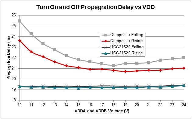
The UCC21520 improves on these integration benefits by having leading performance for propagation delay and delay matching between the high and low side. This reduces losses associated with the switch since it turns on faster and also reduces the required dead time, which is when the higher-loss body diode conducts. These parameters are also less dependent on VDD, so you can relax the design margin for voltage tolerances in the rest of the system, as the bench data in Figure 1 shows. Figure 1 also highlights that the UCC21520 performs significantly more linearly over VDD than its competition.
 Figure 1 TI’s UCC21520 Propagation
Rise/fall Delay with Respect to VDD vs. a Competitor
Figure 1 TI’s UCC21520 Propagation
Rise/fall Delay with Respect to VDD vs. a CompetitorThe micro-inverter is a rapidly growing architecture that converts power from a single PV module to the AC grid and is usually designed for a maximum output power in the range of 180-300W. By distributing the inversion process, the solar array can accommodate much more complex rooftops and enable smaller arrays to be installed that wouldn't typically reach the input voltages of the string-inverter. TI’s basic isolated gate driver, UCC21220, provides an alternative to solar applications where basic isolation is sufficient. Using second-generation capacitive isolation technology to reduce cost via die shrink, UCC21220 not only helps reduce PCB space and system cost but also maintains leading performance for propagation delay and delay matching.
Another device that needs to cross the isolation boundary is the auxiliary power supply. To ensure that the solar inverter is running and “smart” – regardless of the state of the AC utility/load or photovoltaic (PV) panel – requires an isolated power supply to provide bias power for the inverter. Since this stage crosses the isolation boundary, it requires components that cross it as well. Primary-side regulation (PSR), where the output is regulated from an auxiliary winding that is grounded with respect to the primary-side controller rather than an optocoupler, is a great way to reduce components and cost. PSR also has the added benefit of increasing lifetime as well, since it eliminates a notorious point of failure during surge voltages. Primary-side flyback controllers such as the UCC28700 maximize performance and efficiency of the control scheme by implementing advanced algorithms with minimal external circuitry. The UCC28910 expands these advantages by integrating the 700V power FET and controller into a single device, further reducing the size of the bias power supply.
TI solutions can help make cheap, reliable solar energy – enough to power an air conditioner in the middle of a heat wave.
Additional Resources
- Download the white paper, “Isolation in solar power converters: Understanding the IEC62109-1 safety standard”
- Discover TI’s smart grid solutions, including solar energy
- Learn more about PSR flyback converters
- Start designing a 20W auxiliary power supply using the UCC28704 PSR flyback controller with the 20W, 100-425VDC, 85% Efficient, Multi-Output, Auxiliary Power Supply Reference Design.