SSZTA55 may   2017 TLV8544

PRODUCTION DATA  

  1.   1
  2.   2
    1.     3
    2.     What Are PIR Transducers?
    3.     Why Not Power Cycle the PIR Sensor to Reduce Power?
    4.     How Can I Reduce PIR Transducer Current Consumption?
    5.     What Is the Penalty for Starving a PIR Transducer?
    6.     What Type of Circuit Compensates for These Losses?
    7.     What Is the Total Current Consumption of the PIR and Analog Path?
    8.     Conclusion
    9.     Additional Resources

Bahram Mirshab

Wireless, battery-operated, passive infrared (PIR) motion detectors (represented in Figure 1) are gaining popularity in monitoring systems for smart buildings. In these systems, for a single CR2032 coin-cell battery to power the entire circuit close to the circuit’s lifetime, both the PIR sensor and related analog front end (AFE) must have current consumption below 3μA.

In this blog post, I’ll answer some hypothetical questions about PIR transducers and how careful design can significantly lengthen battery life in wireless motion detectors.

GUID-86F7FD2A-88D3-4EB1-8EE7-E6AABAC2B965-low.png Figure 1 Block Diagram of a Wireless Battery-operated PIR Motion-detector System

What Are PIR Transducers?

PIR motion-detector transducers consist of two or more pyroelectric elements within a package. The PIR transducers generate a signal due to a change in the thermal energy pattern caused by a moving object in the field of view. The wavelength of the infrared energy spectrum falls within 1µm (1µm = 10-6 meters) to 1,000µm. The human body’s radiated thermal energy wavelength is between 7µm and 15µm (typically 12µm). PIR motion sensors mainly operate in the far IR wavelength range of 4µm to 20µm.

Why Not Power Cycle the PIR Sensor to Reduce Power?

The PIR sensor takes many seconds to ramp from power up to produce a stable output signal. Thus, power cycling the PIR sensor to lower power consumption is not practical in PIR motion-detector applications because motion is not detectable during power up. Therefore, the sensor and related analog interface signal path must be always on.

How Can I Reduce PIR Transducer Current Consumption?

A simple solution for reducing PIR transducer current consumption is to starve the PIR transducer by using a 3.0V supply (the PIR’s supply range is 2V to 15V) and use a very large value for the bias resistor, R2 (for example, 1.3MΩ) instead of the manufacturer-recommended value of 47kΩ, thus reducing the sensor current consumption from a fraction of a milliamp to about 0.5µA. See Figure 2.

GUID-A53D1ED1-2B06-45B8-B9B5-721144059022-low.png Figure 2 Surface-mount PIR Sensor, Fresnel Lens, Related Passive Components and Output Signal

What Is the Penalty for Starving a PIR Transducer?

Reducing the PIR transducer comes at the expense of decreased sensitivity and higher voltage noise at the sensor output. This is a fair trade-off for a drastically increased battery lifetime. With proper filtering and additional gain in the analog path, you can minimize the drawbacks of the biasing method.

What Type of Circuit Compensates for These Losses?

Figure 3 shows a solution comprising a two-stage active bandpass filter with 3dB corner frequencies of 0.7Hz and 10Hz and a total gain of 94dB. The entire analog path was implemented in the TI TLV8544 quad nanopower (op amp), designed specifically for cost-optimized applications. The values of the components for the PIR interface circuit is provided in Figure 3.

GUID-08B8CD2F-3469-4648-BF92-AD37B89BDB69-low.png Figure 3 The Analog Stages for Filtering and Amplifying the Sensor Signal
GUID-6E8AA62B-6165-4EA7-BEDA-D6317FEDFCFC-low.png Figure 4 Passive Component Values of the PIR Interface Circuit

What Is the Total Current Consumption of the PIR and Analog Path?

You can find the total consumption of the analog interface plus the sensor with the equation below,

GUID-E5AB1FD4-ACA9-46AB-B2A9-5CD335C36A83-low.png

where  is the current consumption of the PIR transducer;    is the leakage current of the reference generator network to ground and  is the current consumption of the TLV8544.

GUID-01FE7A71-B396-493E-90F4-3CF767E17466-low.png

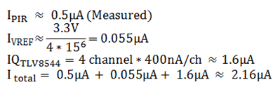
In our solution, the current consumption is 2.16µA, helping to lengthen the lifetime of the CR2032 coin-cell battery.

Conclusion

There is increasing demand to extend the battery life of wireless PIR motion detectors. Power cycling the sensor and related analog interface is not practical, but there are other ways to lower the PIR sensor current consumption drastically. Learn more about PIR design in the application note, “Design of Ultra-Low Power Discrete Signal Conditioning Circuit for Battery-Powered Wireless PIR Motion Detectors.”

Additional Resources

  • Download the TLV8544 nanopower op amp datasheet.
  • Evaluate nanopower op amp functionality as an AFE in a PIR motion-detector system using the TLV8544 BoosterPack and find additional information in the user’s guide.