SSZTAD9 march 2017 LMT87 , LMT87-Q1
Temperature is a big concern in automotive light emitting diode (LED) headlight and taillight applications. LEDs could be exposed to high ambient temperatures while being driven at large currents to produce the necessary brightness. Combined with the large operating current, these high ambient temperatures increase the LED junction temperature, which is typically only rated up to 150°C. High junction temperatures – especially those violating data sheet specifications – risk damage to and shorten LED life times. So what can you do to decrease the junction temperature of the LEDs?

Equation 1 expresses the electrical power dissipated in each LED as:

where Vf is the forward voltage of the LED and ILED is the current through the LEDs. Equation 2 is the general formula for the junction temperature:

where TJ is the junction temperature, TA is the ambient temperature and θJA is the LED junction-to-ambient thermal resistance measured in Celsius per watt.
Substituting the electrical power equation into the junction temperature equation results in Equation 3:

The LED forward voltage and thermal resistance are both characteristics of the LED packaging. Thus, it is clear that at different ambient temperatures, the LED current is the only control parameter that can verify that the LED junction temperature will not violate the maximum specification.
In order to change the current through the LEDs, you need to feed back the ambient temperature measurement to the LEDs’ driving circuit. Designers often use negative temperature coefficient (NTC) thermistors to measure the ambient temperature. Specifically, these NTC thermistors change their resistance with the ambient temperature, so designers measure the voltage across the NTC thermistor and convert that measurement to a temperature.
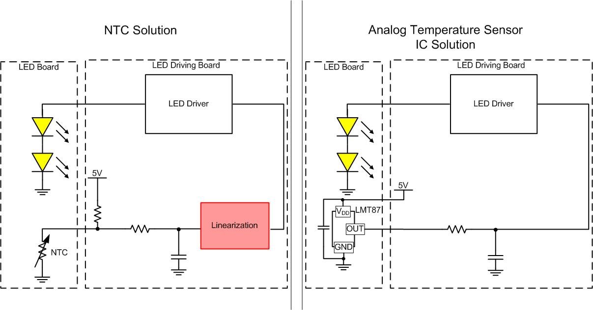
However, a large problem with NTC thermistors is that their resistance decreases nonlinearly with increasing temperature. Moreover, because the resistance decreases nonlinearly, their current consumption increases exponentially across temperature. Since the current through the LEDs is linearly proportional to the temperature, having a nonlinear device requires some external circuitry or a microcontroller to linearize the NTC thermistor voltage and appropriately regulate current through the LEDs.
Using an analog output temperature sensor integrated circuit (IC) such as TI’s LMT87-Q1, which generates a voltage that tracks with ambient temperature, simplifies the total temperature measurement circuitry and enables you to implement a linear thermal foldback curve. Instead of adding external circuitry or a microcontroller to linearize the NTC thermistor output, the output of the temperature sensors feeds back directly into the device generating the current for the LEDs. This means fewer components and no need for a microcontroller to implement thermal foldback.
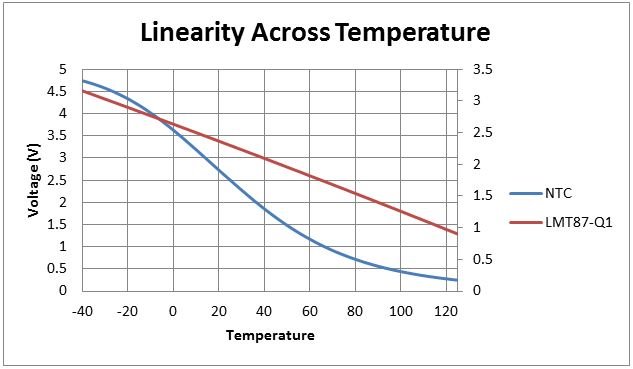
Figure 1 contrasts the use of the NTC thermistor and analog temperature sensor approaches. Figure 2 shows the nonlinearity of an NTC thermistor voltage compared to the LMT87-Q1 output voltage.
 Figure 1 NTC thermistor thermal foldback vs. analog temperature sensor thermal
foldback solution
 Figure 2 Voltage input to LED driver across temperature
Figure 2 shows the differences in the voltage across the NTC thermistor and the output voltage of the LMT87. The NTC thermistor voltage was calculated by putting the NTC thermistor in series with a 10kΩ resistor and an NTC thermistor with values B25/85 of 3435K and R25 of 10kΩ.
While not violating the junction temperature is extremely important, thermal foldback will cause the luminosity of the LEDs to change. Luminosity is effectively how bright the LEDs are. LEDs have characteristic called thermal roll off that basically is reduced light efficiency at high temperatures. Therefore, allowing the LED’s junction temperature to be very high – but not quite violating its maximum specification – could lead to less brightness than anticipated or needed.
Another dominating factor of the LED’s luminosity is the optic used in the lighting module. So while thermal foldback needs to behave linearly, you may need to clamp the curve at different locations. You must take all of these dynamics into account when designing the thermal foldback of a system.
For more information about linear thermal foldback and simple tricks to change the thermal foldback curve using a TI analog temperature sensor, see TI’s Automotive Daytime Running Light (DRL) LED Driver Reference Design with Linear Thermal Foldback TI Design (TIDA-01382).
Additional resources:
- Learn more about automotive lighting
- Different topologies for thermal foldback in Multiple Channel Temperature Sensing for Matrix LED Headlights Reference Design
- Learn more about precision PWM dimming in automotive lighting