SSZTAK1 december 2016 TAS6422-Q1 , TAS6424-Q1 , TAS6424L-Q1
As I recall riding in my dad’s 1957 Chevy, every time he would change the radio to a new station in the AM band, I could hear a lot of static. This loud buzzing sound represents noise from the car’s alternator or ignition system, which either gets transferred into the power supply of the radio or interferes with the radio’s antenna. The noise naturally interferes with the AM broadcast radio signal, which can be heard by the occupants of the vehicle. This is a simple example of electromagnetic interference (EMI).
Back then, audio designs were not sophisticated enough to adequately avoid this interference. Today, car manufacturers are designing vehicles with more and more electronics mounted behind the dashboard in a relatively tight space. This increases the possibility that these electronic circuits can emit interfering signals in close proximity to each other. Ultimately, modern radios and audio amplifiers must provide better immunity from EMI in the AM band to meet these challenges.
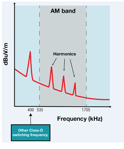
In the U.S., AM radio stations broadcast in the 535 kHz to 1705 kHz frequency band. Existing Class-D audio amplifier designs typically operate with a fundamental switching frequency in the 400-500 kHz range. These Class-D amplifier designs create harmonics that lay directly within the AM band, as shown in Figure 1 below.
 Figure 1 Typical Class-D Amplifier
Harmonics
Figure 1 Typical Class-D Amplifier
HarmonicsThe harmonics create interfering signals that reduce the sensitivity of the AM receiver, thereby hindering the AM radio station’s reception. Some type of EMI avoidance scheme must be implemented on these Class-D amplifier designs to mitigate the effects of these harmonics.
Class-D audio amplifiers need output filters to help maintain a high efficiency. These output filters are made with inductors and capacitors that minimize EMI from the high speed switching transients on the output stages of Class-D amplifiers. The copper-trace lengths on the printed circuit board (PCB) from the amplifier output pins to these output filters create current loops that can act as antennas to also transmit unwanted EMI.
So as car manufacturers add more and more electronics (which increases the possibility of unwanted EMI), infotainment designs need to either implement complex AM avoidance schemes or look for new amplifier designs that address these issues in an innovative manner.
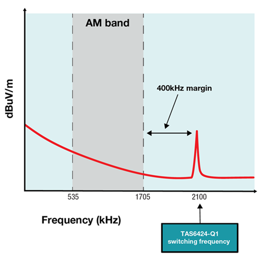
The TAS6424-Q1 is the industry’s first automotive Class-D audio amplifier that operates at 2.1 MHz, providing significant margin above the AM band, as shown in Figure 2 below. This design is also free of any lower-frequency spikes that would interfere in the AM band.
 Figure 2 TAS6424-Q1 Switching
Frequency
Figure 2 TAS6424-Q1 Switching
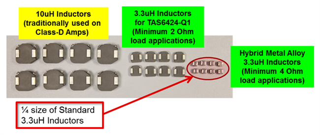
FrequencyA 2.1 MHz switching frequency enables a lower inductance value for the output filter. Since the size of the inductor used in the output filter can be smaller for an equivalent current rating, there is less likelihood of creating additional disruptive current loops. Figure 3 shows the relative size advantage of the 3.3 µH inductors used for the TAS6424-Q1’s output filters, compared to the 10 µH inductors traditionally used on Class-D designs.
 Figure 3 Comparison of Inductor
Sizes
Figure 3 Comparison of Inductor
SizesAutomotive designs will continue to demand solutions that deliver high resolution audio quality in the smallest footprint possible. Technology advancements in Class-D amplifiers continue to improve towards this goal. The high bandwidth feedback loop enabled by the innovative high switching frequency of the TAS6424-Q1, combined with the integrated digital to analog conversion, drives a high quality audio solution.
If you’re starting an automotive infotainment design, be sure to check out the TAS6424-Q1 evaluation module (EVM) that can help you kick-start your next head unit or external amplifier design. The TAS6424-Q1 EVM design will not only help you to demonstrate and evaluate the capabilities of this innovative device, but the schematics, design files and layout guidance can help you rapidly design for optimal EMC performance. I encourage you to hook up your favorite speakers and play your personal music on the TAS6424-Q1 EVM to hear for yourself.
Additional Resources
- Watch a video to learn more about the features of the TAS6424-Q1.
- Download an IBIS model that can help you simulate your device.
- Explore additional mid-power audio amplifiers to suit your design needs.