SSZTAV4 september 2016 UCC24636 , UCC28704
- 1
-
2
- 3
- Why 15 Watts (5V3A)?
- Diode Rectification and PSR Are Widely Used for Adapter Current Lower than 2A
- Synchronous Rectification (SR) Is Preferable to PSR for 5V/3A Adapters with Design Challenges
- How to Make PSR+SR Stable
- A 5V/3A Design with the UCC28704 (PSR Controller) and UCC24636 (SR Controller)
- Summary
- Additional Resources
While planning to write this post, I typed “type-C” into Google Trends. Interest in the term has been rising since 2015 shown in Figure 1.
 Figure 1 Interest over Time on Google
Trends (Keywords: type-C)
Figure 1 Interest over Time on Google
Trends (Keywords: type-C)USB Type-C devices are getting more and more popular in the real world as well, with many prevalent cell phones and tablets adopting USB Type-C. I expect products with USB Type-C to increase rapidly in the coming years.
Why 15 Watts (5V3A)?
Diode Rectification and PSR Are Widely Used for Adapter Current Lower than 2A
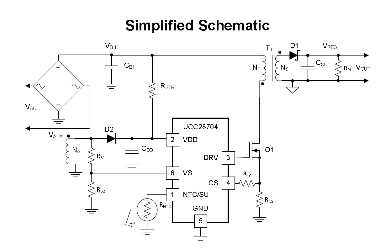
 Figure 2 Typical Application Circuit of
UCC28704 with Diode Rectification
Figure 2 Typical Application Circuit of
UCC28704 with Diode RectificationSynchronous Rectification (SR) Is Preferable to PSR for 5V/3A Adapters with Design Challenges
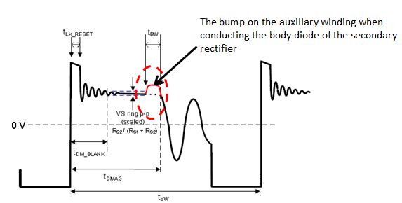
There is a voltage bump on the auxiliary winding when the body diode conducts at the end of the secondary conduction time if using SR, refer to Figure 3. This bump will affect the PSR-detecting mechanism and cause stability problems, which may manifest as abnormal ripple.
 Figure 3 Auxiliary Waveform
Details
Figure 3 Auxiliary Waveform
DetailsHow to Make PSR+SR Stable
A 5V/3A Design with the UCC28704 (PSR Controller) and UCC24636 (SR Controller)
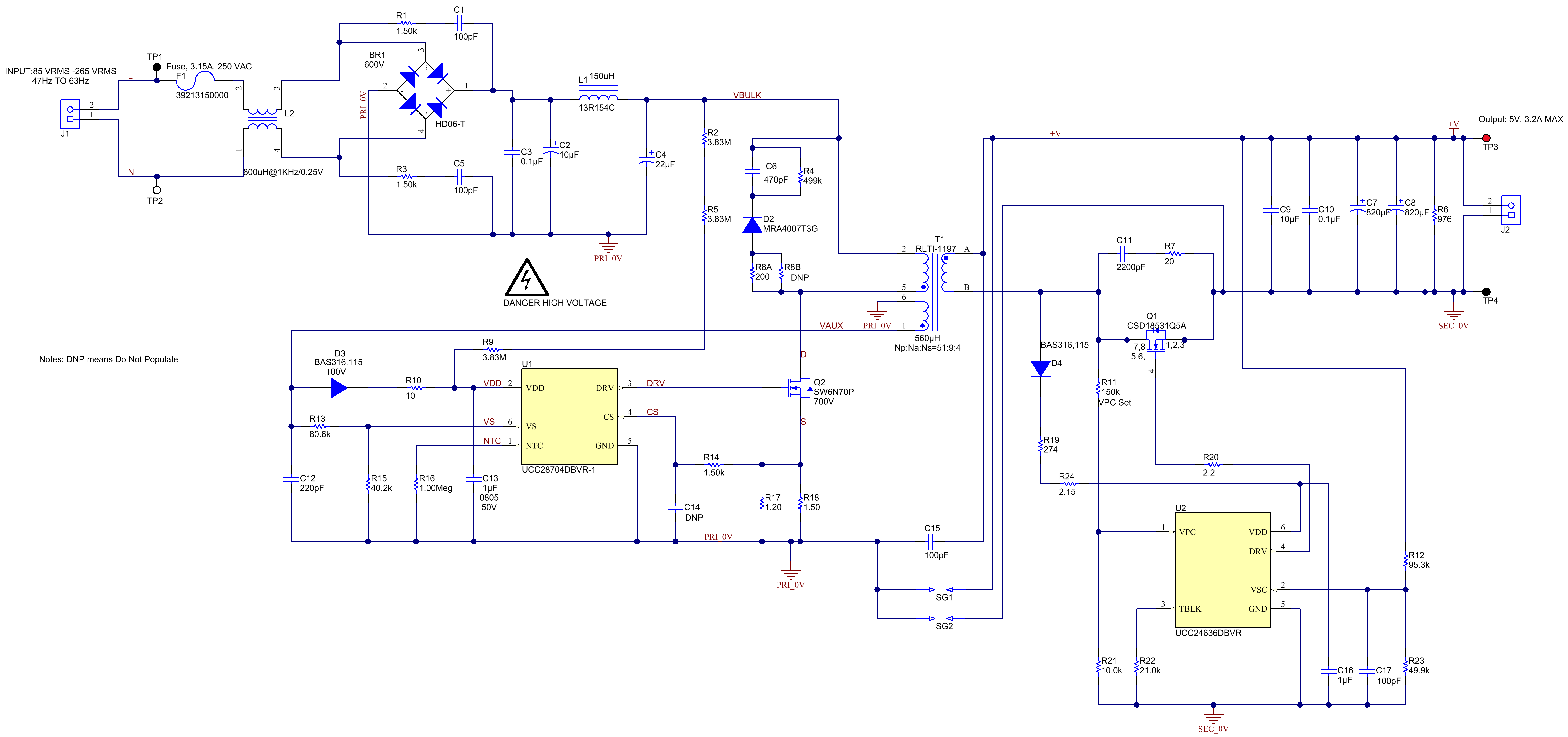
 Figure 4 Universal AC Input to 5V/3A
Ooutput Reference Design DOE6 and COC V5 Tier 2 Compliant TI
Design Schematic
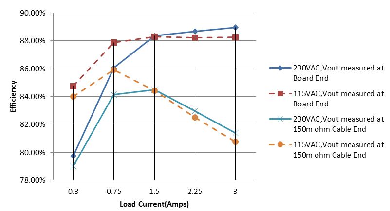
 Figure 5 Efficiency Curves
The four-point average efficiency measured at a 150mΩ cable end with 115VAC and 230VAC inputs are 83.4% and 83.2%. The COC Tier 2 2016 compliance is 81.8% for full load and 72.5% for 10% load.
The board can meet the CoC Tier2 compliance with enough margins even with 150mΩ cable.
Summary
Additional Resources
- Learn more how PSR + SR works in the UCC28704 data sheet and UCC24636 data sheet.
- The Universal AC Input to 5V/3A Ooutput Reference Design DOE6 and COC V5 Tier 2 Compliant (PMP15002) TI Design uses the UCC28704 and UCC24636.
- Read Anwar Sadat’s paper, “Low-cost implementation of USB Type-C.”
- The TI Designs reference design, Universal AC Input to 5V 2A Output Reference Design Tier 2 2016 Compliant (PMP11612), is 5V/2A solution that meets CoC V5 Tier 2.
- Get to know the USB Type-C DFP Charger 5V3A SSR Control Adapter Reference Design