SSZTB32 July 2016 LMV358
My colleague Xiyao Zhang wrote a post last month about changing to a rail-to-rail device after encountering a problem with a circuit. However, what a lot of signal chain designers do not realize is that adjusting signal level, gain and offset of their amplifier could allow them to use their original op amp selection.
There are several types of rail-to-rail operational amplifiers (opamp). Rail-to-rail input (RRI) op amps can operate with any input, from the positive supply rail (VCC) all the way down to ground or to the negative power-supply rail. Rail-to-rail output (RRO) op amps can output a voltage that can approach both the positive supply rail and the negative power-supply rail. Rail-to-rail input and output (RRIO) op amps have both features. Other non-rail-to-rail input and output op amps have limited input and output ranges; however, they have no input crossover distortion and usually have much lower output impedance and lower cost.
In this post, I’ll discuss four popular amplifier topologies:
- Inverting amplifiers.
- Noninverting amplifiers.
- Differential amplifiers.
- Unity-gain buffers.
Inverting amplifiers are good for minimizing total harmonic distortion. Figure 1 shows the basic schematic.
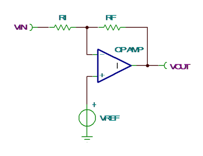 Figure 1 Inverting Amplifier
Because the input common-mode range is a fixed voltage set by the designer, RRI isn’t necessary. RRO is helpful if the output needs to span the whole VCC range.
Noninverting amplifiers preserve input signal polarity. Figure 2 shows the basic schematic.
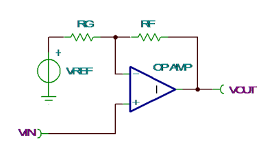 Figure 2 Noninverting Amplifier
The required input common-mode range will be less than output range. The reduced input range for differential amplifiers means that you may not need RRI. RRO is still helpful if the output needs to span the whole VCC range.
For operation across the full VOUT range of the op amp, both output voltage low (VOL) and output voltage high (VOH) will have an inverting pin voltage within the valid input common-mode range. The inverting pin voltage for VOL is VOL + RF /(RF + RG) * (VREF - VOL). The inverting pin voltage for VOH is VOH + RF / (RF + RG) * (VREF - VOH).
Differential amplifiers are great for floating or balanced input sources. Figure 3 shows the basic schematic.
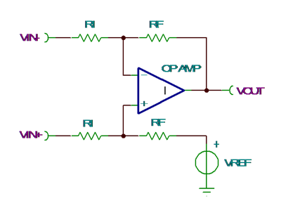 Figure 3 Differential Amplifier
The differential gain, noninverting input range and VREF reference voltage set the necessary input common-mode range. The input common-mode voltage is (VREF + VIN+ * G)/(G+1), where G is the differential gain of the circuit, VREF is the termination voltage for noninverting divider and VIN+ is the noninverting differential input. Lower gains reduce the required input common-mode range.
You should test the minimum and maximum VIN+ using the formula in the paragraph above to verify that the input common-mode range is not exceeded. RRO is helpful if the output needs to span the whole VCC range.
Unity-gain buffers prevent signal loading and provide low-output impedance. Figure 4 shows the basic schematic.
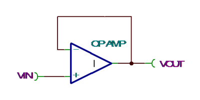 Figure 4 Unity-gain Buffer
For this configuration, the output will faithfully track the input only for the voltages specified by the op amp’s input and output voltage range.
Output swing is limited by output range, which is specified in the data-sheet specifications for VOL and VOH . Trying to exceed the input range will result in output signal clipping or may have an output step to maximum VOH. Figure 5 shows the LMV358 which can either clip the output (blue curve) or output step(red curve).
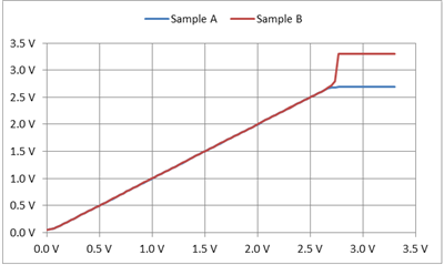 Figure 5 Rro LMV358 vOUT Vs.
vIN Using a Unity-gain Circuit, Where vCC =
3.3V
Figure 5 Rro LMV358 vOUT Vs.
vIN Using a Unity-gain Circuit, Where vCC =
3.3VAchieving the full-range output using a RRO device would require resistively attenuating the input signal to meet the input common-mode range, and then amplifying by the same factor. The problem with this method is that you will need four resistors instead of none. This method also reduces the input impedance, which can defeat the purpose of adding a unity-gain buffer.
Therefore, it is best to have the previous stage provide an output signal that is within the input and output range of the op amp.
After adjusting the signal level, gain, or offset you just might find out that the op amp is compatible after all. Sign in to join the conversation.
Additional Resources
- Check out TI’s broad portfolio of general-purpose amplifiers.
- Learn more about rail-to-rail input operation from this EDN article.
- Check out TI’s portfolio of fully differential amplifiers.