SSZTBE5 April 2016
Insulation deterioration is one of the primary causes of electrical-equipment failure in motors, high-voltage transformers and generators. Insulation failure can cause dangerous voltages, fires, high-fault currents and explosions, damage to equipment and property, personal injury, and fatal accidents. The main causes of insulation failure are dielectric contamination, temperature cycling, excessive overloads, excessive voltage stress due to overvoltage, and aging.
Let’s look at two different examples of insulation failures. Figure 1 shows a defective stator winding of a welding alternator and burnt coils at the connection side of the winding. Figure 2 shows a transformer that suffered catastrophic failure due to damaged insulating paper, caused by a lack of timely preventive maintenance.
") Figure 1 Defective Stator Winding of a
Welding Alternator (Image Source: WindingPhotos)
Figure 1 Defective Stator Winding of a
Welding Alternator (Image Source: WindingPhotos)") Figure 2 Catastrophic Failure of a
Transformer (Image Source: OilRegeneration.com)
Figure 2 Catastrophic Failure of a
Transformer (Image Source: OilRegeneration.com)Insulation tests can identify deterioration of insulation before any failure occurs.
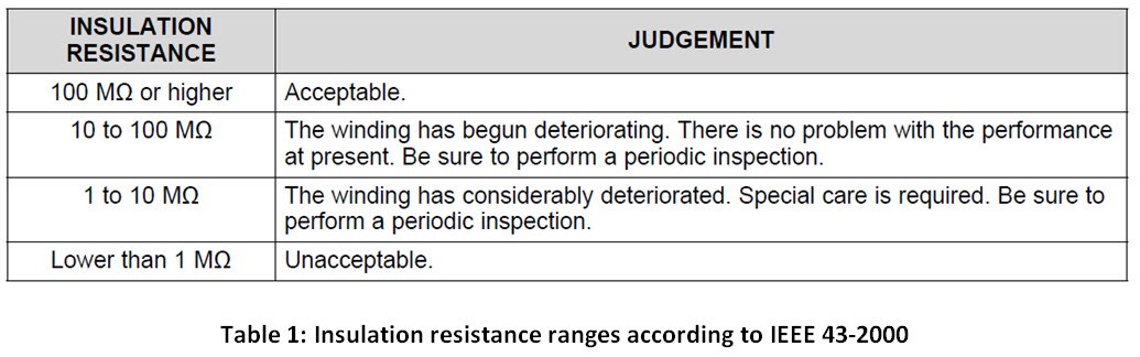
The Institute of Electrical and Electronics Engineers (IEEE) Recommended Practice for Testing Insulation Resistance of Rotating Machinery (IEEE 43-2000) describes a procedure for measuring insulation resistance, including typical insulation-resistance characteristics of rotating machinery windings and how these characteristics indicate the winding condition. The standard recommends the minimum acceptable values of insulation resistance for alternating current (AC) and direct current (DC) rotating machine windings. According to IEEE 43-2000, the typical insulation resistance indicating an acceptable condition is 100MΩ and above. Using this measurement as a base, the IEEE standard sets the ranges listed in Table 1.
Applications and Use Case
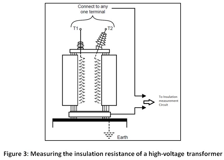
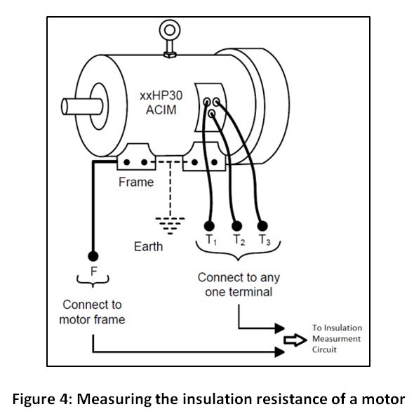
Insulation measurement is important for end-equipment such as transformers, solar inverters and industrial motor drives (variable speed AC/DC drives and servo drives); see Figures 3 and 4.
Using a resistor divider is a simple way to measure the insulation resistance. Figure 5 shows a TINA-TI™ simulated circuit for this approach, where two series resistors (R12 and R2) are connected in parallel with the insulation resistance (Riso). The total current flowing through the parallel combination is limited by the value of R1, R4 and the DC input (typically 500V according to IEEE 43-2000). The voltage across R2 (which is result of current flow) is measured (VM1), as explained in Fig. 6.
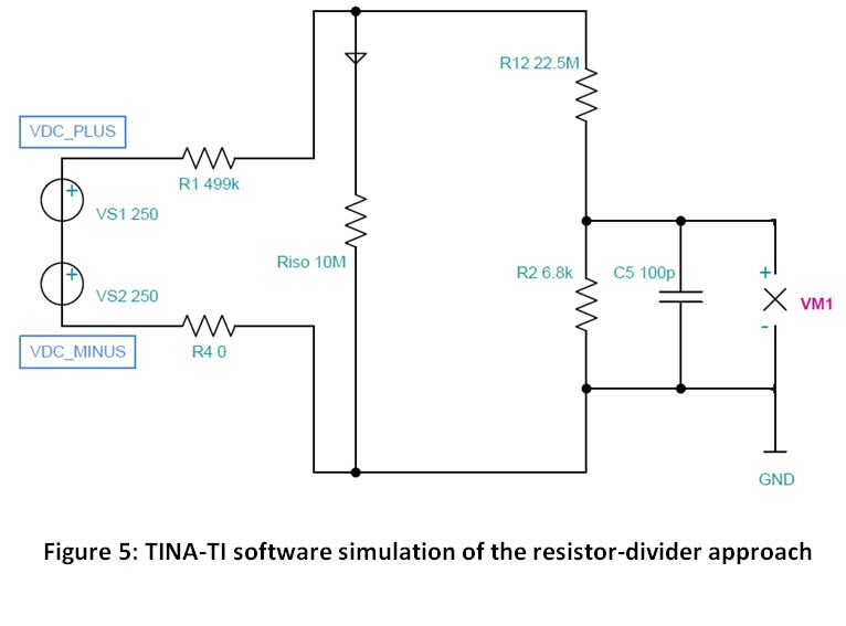
Figure 6 is the measurement graph from the TINA-TI simulation. Due to the ratio of resistors, the voltage across R2 does not vary linearly with the insulation resistance (Riso). The measured value of voltage VM1 is almost saturated, with an insulation resistance value greater than 15MΩ.
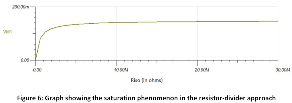
Figure 7 shows the accuracy graph for the resistor-divider approach. The percentage accuracy is < 1% for a range of 0Ω to 22.49MΩ.
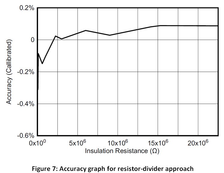
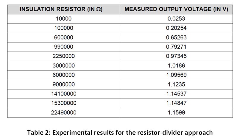
Table 2 lists the experimental results of this approach. As you can see, the measured output is almost 3mV to 4mV different from the previous value. This difference in value means that a high-resolution analog-to-digital converter (ADC) is required when using the resistor-divider approach, which adds cost to the system.
In my next post, I will look into another method that can offer good accuracy in the entire 0MΩ-to-100MΩ range of insulation resistance.
Additional Resources
- View the technical documents for the TI Design reference design: Leakage Current Measurement for Determining Insulation Resistance.
- View the IEEE standard.
- Get acquainted with TINA-TI™ Analog simulation program