SSZTBG6 april 2016
The product line I work in develops multi-rail power supplies for LCDs and AMOLED displays. It is common for such supplies to feature one or more inductive converters, plus a couple of charge pumps to generate additional low-power output voltages. Charge pumps are ideal for these applications because they’re comparatively simple and inexpensive.
Figure 1 shows a charge pump that uses the switch node of a boost converter to drive the flying capacitance. To avoid disrupting boost converter operation, it’s a good idea not to load the switch node too much. A good rule of thumb is to make sure that the charge pump’s output power is less than 10% to 20% of the boost converter’s output power.
 Figure 1 Driving a Charge Pump from the
Switch Node of a Boost Converter
Figure 1 Driving a Charge Pump from the
Switch Node of a Boost ConverterIn this circuit, the boost converter’s
switch node generates a rectangular drive waveform whose duty cycle, D, is
approximately equal to  , where VI is the input
voltage of the boost converter. Diodes D1 and D2 form a single-pole, double-throw
(SPDT) switch.
, where VI is the input
voltage of the boost converter. Diodes D1 and D2 form a single-pole, double-throw
(SPDT) switch.
The output voltage of this circuit is given by Equation 1:
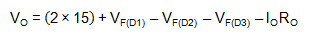
where VF is the forward voltage across the diodes, IO is the output current and RO is the output resistance of the charge pump.
I described in my last post how RO reaches a minimum value when the flying capacitor is larger than some critical value, and here it is again in Figure 2. The main difference when using the switch node to drive a charge pump is that the duty cycle of the DC/DC converter has an effect on the value of RO(min), which increases whenever D moves away from 0.5 (see Figure 3). These parameters change too:
- Peak current during the charge
phase is
 and during the discharge phase
is
and during the discharge phase
is  .
. - Output voltage ripple is
 .
.
 Figure 2 Output Impedance vs. Flying
Capacitance
Figure 2 Output Impedance vs. Flying
Capacitance") Figure 3 The Effect of Duty Cycle on
RO(Min)
Figure 3 The Effect of Duty Cycle on
RO(Min)For all practical purposes, the output
impedance of the switch node is close to zero. Which is good, right? Actually, it’s
not, because very low drive impedance can cause high peak currents to flow into the
switch node, which can sometimes screw up boost converter operation. This is
especially true during startup, when the flying capacitor must charge up over a
number of cycles from 0V to almost 15V. To get around this, it is good practice to
include a resistance of a few ohms (RFLY) in series with the flying
capacitor, in which case the minimum output resistance is  .
.
Of course, you can use the switch node equally well to generate negative output voltages (see Figure 4).
 Figure 4 Boost Converter Driving an
Inverting Charge Pump
Figure 4 Boost Converter Driving an
Inverting Charge PumpThe math for this circuit is similar to the voltage doubler case:

where once again 
There are various ways to regulate the output voltage of a discrete charge pump, but the easiest by far is to let the charge pump run open loop and simply post-regulate with a linear regulator. There’s no efficiency hit using this method – all but the most sophisticated charge pump regulation techniques burn off unused power – and it’s easier to stabilize. The alternative circuit shown in Figure 5 is attractive because you can use a positive regulation circuit to control a negative output voltage, but regulating the charge pump’s output voltage directly in this way often causes the charge pump’s control loop to “fight” with the boost converter’s control loop. One way to solve this problem is to make sure that the charge pump’s crossover frequency is much lower (at least five times lower, say) than the boost converter’s. Using a linear post-regulator avoids this problem altogether.
 Figure 5 Regulating an Inverting Charge
Pump
Figure 5 Regulating an Inverting Charge
PumpThe examples in this post show charge pumps running from the switch node of a boost converter, but you could of course use other converter topologies. The main advantage of the switch node in a boost converter is that its amplitude is constant. This is not the case when using the switch node of a buck or buck-boost converter, in which the amplitude varies with the input voltage. Of course, if you’re running from a regulated input voltage you won’t have this problem, whichever topology you use.
Correct charge pump operation relies on the drive signal being permanently available. This is not guaranteed if the charge pump runs from a converter that uses a pulsed-frequency mode (PFM) at low output currents to improve efficiency. During PFM operation, a DC/DC converter switches in bursts; during the pauses between switching bursts, the charge pump’s output voltage will decay because its output capacitor has to supply all of the output current. It’s much better if the DC/DC converter driving the charge pumps continues to operate in pulse-width modulation (PWM) at all times.
Similarly, correct charge pump operation can be disturbed if the boost converter inductor current ever goes discontinuous, in which case the charge pump’s drive signal disappears. If the boost converter’s output current is high enough, inductor current may stay continuous. Alternatively, if the converter uses synchronous rectification, the inductor current may stay continuous, even at low output currents. (Take care, however: Some synchronous converters, particularly those aimed at low-power applications, turn off the synchronous rectifier when the inductor current is zero and enter discontinuous conduction mode (DCM)).
In the final installment of this series, I’ll take a look at multistage charge pumps.