SSZTBI6 March 2016
Ceramic capacitors are well-suited to manage ripple current because they can filter large currents generated by switched-mode power supplies. It is common to use ceramic capacitors of different sizes and values in parallel to achieve the optimum result. In such a case, each capacitor should meet its allowable ripple-current rating.
In this post, I’ll use a buck converter as an example to demonstrate how to select ceramic capacitors to meet ripple-current requirements. (Note that bulk capacitors such as aluminum electrolytic or tantalum capacitors have high equivalent-series-resistance (ESR). When put in parallel to ceramic capacitors, these bulk capacitors are not designed to take a large ripple current. Thus, I won’t discuss them here.)
Figure 1 shows a basic circuit of a buck converter. The converter input current, iIN_D, consists of a large ripple current, ΔiIN_D.
 Figure 1 The Basic Circuit of a Buck
Converter
Figure 1 The Basic Circuit of a Buck
ConverterThe buck converter parameters are:
- Input voltage (VIN) = 12V.
- Allowable input ripple voltage (ΔVIN) < 0.36V.
- Output voltage (VO) = 1.2V.
- Output current (IO) = 12A.
- Inductor peak-to-peak ripple current (ΔIpp) = 3.625A.
- Switching frequency (FSW) = 600KHz.
- Temperature-rise limit of the ceramic capacitors < 10°C.
Figure 2 shows the input ripple-current waveform.
 Figure 2 Input Ripple-current
Waveform
Figure 2 Input Ripple-current
WaveformTo meet the ripple-voltage requirement, the effective capacitance of the ceramic capacitor should be greater than that calculated with Equation 1:
With the converter parameters and requirements, Cce_total should be greater than 5µF.
The selected ceramic capacitors must also meet the ripple-current limitation. Equation 2 calculates the root-mean-square (RMS) value of the ripple current:
Given that IO = 12A, ΔIpp = 3.625A and D = 10%, the RMS value of the input ripple is 3.615ARMS.
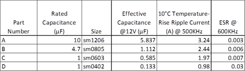
Table 1 lists the characteristics of available ceramic capacitors with the proper voltage rating. These capacitors are of 10% tolerance.
|
While one piece of Capacitor A provides sufficient effective capacitance to meet the ripple-voltage requirement, its ripple-current rating of 3.24ARMS is slightly less than that generated by the converter. While adding another piece of Capacitor A meets the requirement, it occupies more space and costs more than other smaller capacitors. The question is which capacitor or capacitors should be added. To answer that question, I conducted an analysis on ripple-current distribution. Figure 3 is a simplified schematic of two capacitors in parallel with an AC current source.
 Figure 3 Schematic of Ripple-current
Distribution
Figure 3 Schematic of Ripple-current
DistributionAccording to Ohm’s law, current distribution should abide by Equation 3:
Ceramic capacitors have small ESR. Figure 4 shows two examples.
 Figure 4 Ceramic Capacitor Impedance |Z| and ESR R over Frequency
For frequencies lower than 1MHz, you can approximate the impedance of a ceramic capacitor, XC, by XC = 1/(jωC). Thus Equation 3 simplifies into Equation 4. According to Equation 4, ripple current is in proportion to the effective capacitance:
When multiple capacitors are in parallel, the capacitor with the lowest allowable ripple current over effective-capacitance ratio, IRMS-over-C, will hit the ripple-current rating first. Assuming that C1 has lower IRMS-over-C than C2, Equation 5 estimates the total allowable ripple current, I∑_RMS_Allow:
When C1 hits its allowable ripple-current rating, the ripple current through C2 will not exceed its allowable ripple current, as Equation 6 shows:
In order to have I∑_RMS_Allow ≥ IIN_AC_RMS, the additional capacitance should be greater than that calculated by Equation 7:
Tol. is the capacitance tolerance of these ceramic capacitors. When tolerance is included in the calculation, the worst-case ripple current of the bottleneck capacitor would not exceed its rating.
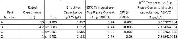
I listed the IRMS-to-C ratio as a parameter in Table 2.
|
Capacitor A has high effective capacitance at 12VDC bias. To meet the ripple-current requirement, you should add an additional capacitor or capacitors to meet ripple current requirement. Since Capacitor A has the lowest IRMS-to-C ratio, the added effective capacitance, Cadditional, should be greater than that calculated with Equation 8:
There are two options. The first option is to add one piece of Capacitor B. The second option is to add one piece of Capacitor C and two pieces of Capacitor D. Both options provide sufficient additional effective capacitance and occupy similar printed circuit board (PCB) areas. Since the latter option is more cost-effective, I chose the second option.
To verify my hypothesis, I conducted a PSPICE simulation; Figure 5 shows the circuit I used. I also used the nominal values of the capacitors for a typical case.
 Figure 5 Ripple-current Distribution Simulation Circuit
Figure 6 shows the simulation waveforms and the RMS values for the ripple currents of the capacitors, which are:
- ICA_RMS_typ = 3.13ARMS.
- ICC_RMS_typ = 0.353ARMS.
- ICD_RMS_typ = 0.081ARMS.
- VIN ripple voltage = 0.299V.
 Figure 6 Simulated Ripple-current Waveform of Each Ceramic Capacitor
I then used capacitor values that would render a worst case for the Capacitor A, the bottleneck capacitor.
The RMS values of the ripple currents of the capacitors are:
- ICA_RMS_max = 3.206ARMS.
- ICC_RMS_min = 0.306ARMS.
- ICD_RMS_min = 0.070ARMS.
Each capacitor meets its allowable ripple-current rating.
Using ceramic capacitors of different sizes in parallel provides a compact and cost-effective way to filter large ripple current. But with different capacitances and ripple-current ratings, it is difficult to determine the total allowable ripple current. In this post, I proposed a parameter called allowable ripple current over effective-capacitance ratio, IRMS/C. IRMS/C helps you find the bottleneck capacitor for the allowable ripple current. Use the lowest IRMS/C to estimate the total allowable ripple current and to select additional capacitors. Please be aware that PCB parasitics could greatly affect circuit performance. This method provides a good estimation; however, you must verify designs empirically.
Additional Resources
- Explore more power-supply topics.
- Watch Power Tips videos to help with your design challenges