SSZTBJ6 march 2016 THVD1520
As my colleague Bart Stiller mentioned in the first installment of this series, RS-485 is a multipoint differential bus, shown in Figure 1. This means that all of the nodes on the bus share one common transmission medium, and therefore every node placed onto the bus adds a load in parallel to all of the existing network transceivers and termination resistors. As the total number of nodes increases, the loading on each and every driver increases as well.
 Figure 1 Multipoint RS-485 Bus
To set practical and measureable limits for RS-485 output drivers, the Telecommunications Industry Association (TIA)/Electronic Industries Alliance (EIA)-485 standard created a hypothetical “unit load,” and then limited the maximum number of unit loads that can be presented to any driver on an RS-485 bus to 32. The standard states that a driver must be able to drive a minimum 1.5 differential signal across a maximum of 32 unit loads in parallel with two 120-Ω termination resistors.
You can determine the unit-load parameter by sweeping the input voltage from -7 to +12 V on one bus pin, with the other bus pin held at ground, and then measuring the input leakage current. You will measure both bus pins individually, with the transceiver both in a powered and unpowered state. As you can imagine, the input leakage current depends on the input voltage; thus, when calculating the unit load, Equation 1 uses the worst-case ratio of input voltage to leakage current:
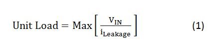
where VIN {-7 … + 12 V}.
In Figure 2, the bounds of -7 and +12 V in the standard are meant to allow up to ±7 V of ground-potential difference (GPD) between a driver output and a receiver, with the driver’s output voltage varying between GND and 5 V. Therefore, -7 V represents a receiver seeing a respective driver pin driving the bus low with a -7 V GPD, while +12 V represents a receiver seeing a respective driver pin driving the bus high with a +7 V GPD.
 Figure 2 Maximum GPD of a standard
RS-485 transceiver
Figure 2 Maximum GPD of a standard
RS-485 transceiverOne unit load is equivalent to 1 mA of input leakage current at +12 V. This load represents a single-ended load with respect to ground. Another easy way to think of the unit load is the equivalent of a 12 kΩ resistance from either the A or B bus pins (and the Y and Z pins for full-duplex transceivers) to ground.
Once you’ve found the maximum ratio of input voltage to leakage current, you can calculate the equivalent unit load by dividing that ratio by 12 kΩ, expressing the result in terms of a fraction of the unit load.
Using this unit-load ratio, you can then easily calculate the maximum number of any variety of transceivers that the network can handle. For example, if you were looking at the THVD1520 RS-485 transceiver, which has a one-eighth unit-load input impedance, you would be able to place a theoretical maximum of 256 nodes on the network, as shown in Equation 2:
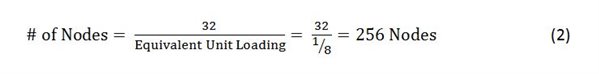
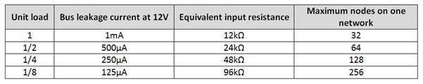
Table 1 shows the relationship between unit load, bus leakage current, equivalent input resistance and the maximum number of devices that can be on the network for a few typical unit loads.
|
If you recall from the second installment in this series, the common-mode load for an RS-485 driver-output test circuit is 375 Ω; see Figure 3. That is because it is the equivalent of 32 unit loads (12 kΩ) in parallel.
 Figure 3 RS-485 Driver-output Test
Circuit with Common-mode Load
Figure 3 RS-485 Driver-output Test
Circuit with Common-mode LoadMoreover, if you are trying to figure out how many transceivers you can place on your network, this data sheet will have a unit-load parameter or a maximum input leakage current that can be used for calculating the unit load. The smaller the unit load, the more devices you can place onto the network.
In the next installment of this series about RS-485 basics, I’ll discuss standard terminations and how to use receiver fail-safe terminations.
Additional Resources:
- Read the RS-485 basics series on the Analog and Industrial technical articles.
- Search our complete RS-485 portfolio.
- Share questions and knowledge with fellow engineers in the TI E2E Community Industrial Interface forum.