SSZTBY2 november 2015 TPS23751 , TPS23752 , TPS23753 , TPS23754
The flyback is the most commonly used isolated DC/DC converter in power over Ethernet (PoE) powered device (PD) designs, delivering power up to 25.5W in many Ethernet-based products such as wireless access points, IP phones and security cameras.
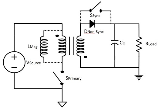
Figure 1-1 shows a simple flyback power stage. The flyback works by first charging the magnetizing inductance and storing the energy in the air gap of the power transformer when the primary switch is on. When the primary switch is off, the magnetizing inductance reverses voltage and forward-biases the diode, allowing energy to be delivered to the load.
 Figure 1-1 Flyback Converter Power
Stage
Figure 1-1 Flyback Converter Power
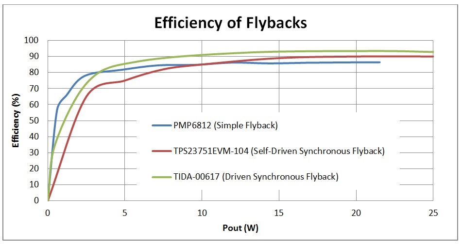
StageThe benefit to using a flyback is its simplicity and ease of design, which makes it a low-cost solution. However, due to the high peak and RMS currents, the MOSFET and output-rectifier diode in the flyback have high conduction losses, which results in relatively lower efficiency. The Class 4, Cost-Optimized, Flyback Converter for POE Applications TI Designs reference design (PMP6812) demonstrates how to use the TPS23754 PoE PD in a low-cost, simple diode-rectified flyback solution to achieve an efficiency of 86% at 25W. Note that the reference design has a 12V output, which will have higher efficiency than a 5V output. Comparably, a 5V output-diode-rectified flyback can yield ~80% efficiencies at this range of power.
In a synchronous flyback converter, the diode is replaced with a low RDSon MOSFET (SSynch in Figure 1-1) to allow for a dramatic reduction in conduction losses and thus much higher efficiencies, which are needed for higher-power PoE applications. A common implementation of the synchronous flyback is a self-driven topology that adds a winding to the power transformer to generate the synchronous gate-drive signal. For example, the TPS23751EVM is a self-driven synchronous flyback PoE PD solution that uses the TPS23751 to achieve a converter efficiency of 90% at 25W.
As PoE equipment becomes more sophisticated with special features (for example, tilt, pan and zoom in security cameras), the power delivered to the PoE PD – as much power as possible – must be converted as power to the load. Thus, any extra percentage of efficiency is desirable.
Without switching (pun intended) to a different topology like an active clamp-forward converter, a driven synchronous flyback is a viable solution. Rather than using an extra winding on the flyback transformer, the gate-drive signal of the DC/DC controller (many times internal to the PoE PD IC) drives the synchronous FET through a gate-drive transformer. Now, you can eliminate the amount of shoot-through losses present in the self-driven approach. The result is an overall more efficient flyback design.
The Class 4 High-Efficiency Driven Flyback Converter (5V/5A) for PoE PD Applications TI Designs reference design (TIDA-00617) is a driven synchronous flyback PoE PD solution that uses the TPS23751 to achieve a converter efficiency of 93% at 25W.
 Figure 1-2 Relative Efficiencies of Three
Flyback Topologies Implemented in PoE PD Applications
Figure 1-2 Relative Efficiencies of Three
Flyback Topologies Implemented in PoE PD ApplicationsFigure 1-2 shows the relative efficiencies around the Class 4 power levels for three different flyback configurations. You can also browse many more PoE PD converter solutions using the PoE widget to narrow down your search and find complete solutions for your next project.
Additional Resources
- Read the Power Supply Design Seminar paper, “Under the Hood of Flyback SMPS Designs.”
- Download the application report, “Designing with the TPS23753 Powered-Device and Power Supply Controller.”
- Order the TPS23752 evaluation module.
- Check out these reference designs: