SSZTBZ3 November 2015 INA188
When building analog signal chains for precision, you should consider several factors during component selection to maintain accuracy in your resulting measurements: offset, offset drift (with temperature), gain error or linearity, and low-frequency noise. In many high-precision applications, the source signal is very small and requires a great deal of gain to adjust the signal level. This is very common in precision data-acquisition systems, where you must adjust the source signal to match the input range of an analog-to-digital converter (ADC).
At first glance, you might select a typical operational amplifier, not realizing that the offset voltage is input referred – and thus affected by gain. When you add a significant amount of gain such as A=100, the offset voltage may add significant error. For example, if you have a typical amplifier with an input offset of 3mV and a gain of 100, you have a potential full-scale error of 300mV, or roughly one-third of a volt. For a 3.3V input ADC, the system would have an error of roughly 10%.
Over the years, designers have made great strides in precision amplifier design to remove offset and calibrate it over temperature, resulting in excellent drift numbers. But with improved precision, other factors begin to dominate – mostly driven by amplifier architecture or physics and lumped together in the category of “noise,” or electrical uncertainty.
A group of precision amplifiers called chopper-stabilized amplifiers use an alternative switched path to null the input offset. This technique does an excellent job of removing offset and tracking with temperature, but can also introduce chopping noise. The noise tends to be above 10kHz, however, so you can easily filter it out of most precision applications where the time constant is fairly long (such as when measuring temperature).
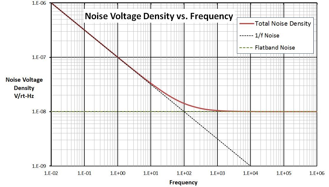
There is another insidious noise source called 1/f (one-over-f) noise, also known as flicker noise. As the name implies, flicker noise increases with decreasing frequency – typically in the region of low-frequency precision measurements. The noise power has an average slope of -10db/decade and is caused by various physical properties of the amplifier’s semiconductor material (see Figure 1). The 1/f noise is unbounded and increases with time, making the measurement of this noise source very difficult – unless you want to wait years to get your answer. This noise source dominates at low frequency, and like my earlier input-offset example, is also a function of gain. So in high-gain systems (A > 100), this noise can be significant.
 Figure 1 The Intersection of 1/F Noise
and Wideband Noise Lines Form the 1/F Corner Commonly Found in Most Amplifiers.
the Low-frequency Noise Grows Inversely with Frequency and Is Problematic in
High-precision Systems.
Figure 1 The Intersection of 1/F Noise
and Wideband Noise Lines Form the 1/F Corner Commonly Found in Most Amplifiers.
the Low-frequency Noise Grows Inversely with Frequency and Is Problematic in
High-precision Systems.In an effort to combat this noise source, a new class of devices has arrived that has solved the 1/f noise issue. The INA188 is an instrumentation amplifier that not only has exceptional world-class offset and drift specifications, but eliminates the 1/f corner where the flicker noise intersects the wideband noise, providing a flat noise floor down to 0.1Hz. This can help improve applications such as strain gauges that use bridge topologies or other high-precision measurements used in process control. These types of measurements typically use very high levels of gain and suffer from the increased low-frequency flicker noise found in most precision amplifiers.
If you want to know more about 1/f noise and its implications, check out this excellent blog post, which includes the Excel spreadsheet used to create Figure 1.
Additional Resources
- Read the data sheet to find out more about the INA188 instrumentation amplifier.
- Check out the three-terminal PLC reference design featuring the INA188.
- Learn more about TI’s precision-amplifier portfolio and find technical resources.
- Explore TI’s entire portfolio of amplifier ICs and find technical resources.