SSZTC48 september 2015 UCC25600
Have you ever wondered why the measured switching frequency (fsw) of your LLC series resonant converter (LLC-SRC) is far from your calculations in some designs?
To understand the reason for the discrepancy, let’s start with a basic isolated LLC-SRC, shown in Figure 1. A basic isolated LLC-SRC consists of a half bridge (S1, S2), a resonant capacitor (Cr), a resonant inductor (Lr) and an ideal transformer (with Lm as magnetizing inductance). Most AC/DC power-supply designers linearize this basic isolated LLC-SRC with sinusoidal approximation to get the input-to-output voltage gain and predict switching frequencies under different conditions. The calculations have been proven close to the actual measurements when fsw is close to the higher resonant frequency (fr=1/(2π(LrCr)0.5).
 Figure 1 Basic Isolated LLC Series
Resonant Converter
Figure 1 Basic Isolated LLC Series
Resonant ConverterHowever, you may notice that in some of your designs, the measured switching frequencies are far away from the calculation results using the linearization process mentioned above. So why is there still a discrepancy between the calculation and measurement results?
If you check the assumption of the linearization process carefully, you will notice that it assumes an ideal transformer without leakage inductance. Thus, given inevitable leakage inductance in a real transformer, there will be a discrepancy between your measurements and your calculations. The discrepancy increases significantly when a single integrated transformer, such as a transformer leakage inductance, is utilized as the resonant inductor Lr, because the magnetizing inductance of the transformer is no longer much greater than its leakage inductance. To fix this, you will need to remodel the transformer using a transformer model like the one shown in Figure 2.
 Figure 2 Isolated LLC Series Resonant
Converter with Integrated Transformer
Figure 2 Isolated LLC Series Resonant
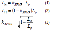
Converter with Integrated TransformerIf you define the primary inductance of the transformer when the output windings are open to be Lp and the leakage inductance of the transformer when the output windings are shorted to be Llk, you can express the relationship between Lm, Lr1, Lp and Llk as Equations 1 to 3. Where kXFMR is the transformer coupling coefficient.
By using the integrated transformer model in Figure 2 and equations above, you can check the difference between the calculations and measurements.
The Low-Line Wide Input LLC Resonant Converter for Consumer Electronics (12V at 10A) TI Designs reference design operates with a wide input range (100VAC to 132VAC) and includes an integrated transformer. To maintain good output regulations, the ratio of Lp/Llk (86.9µH/22.3µH = 3.9) in the reference design is lower than common off-line LLC-SRC designs. The low Lp/Llk ratio makes the transformer far from ideal, hence, this design is a good example to show how much discrepancy you will get if using the model in Figure 1 on an LLC-SRC with a badly-coupledl transformer.
Figure 3 shows the calculation results based on Figure 1 (assuming Llk = Lr and Lm = Lp-Llk), as well as Figure 2’s model and measurement results. The 12V output was loaded with 6A during the test.
 Figure 3 Comparison between Calculated
and Measured Switching Frequencies of PMP8762
Figure 3 Comparison between Calculated
and Measured Switching Frequencies of PMP8762As you can see, the calculation results using the transformer model in Figure 1 are far from the actual measurements. Instead, by using a proper transformer model in Figure 2, the calculation results are much closer to the actual switching frequency.
So the next time you begin an LLC-SRC design, once you’ve decided to use an external Lr with a well-coupled transformer or single integrated transformer, be sure to use the correct transformer model.