SSZTC83 September 2015 ADC3444 , TPS54120 , TPS7A47
In my previous posts, I’ve discussed designing a real-world power supply. Now, let’s use what we know about the analog-to-digital converter (ADC) power-supply rejection (PSR) and signal-to-noise ratio (SNR), coupled with the DC/DC converter frequency content we need to suppress, to find the best possible power-supply solution. “Best” not only implies performance, but also includes printed circuit board (PCB) area and solution cost.
In my “Using a DC/DC converter to power an ADC” post, I evaluated the impact of a minimally loaded medium-current DC/DC converter. While this approach cannot be implemented cost effectively and occupies a lot of precious PCB area, it did demonstrate the minimum impact a DC/DC converter will have in the system. But how would the system react if a 3A DC/DC converter were shared between the ADC and an additional 2A load? Building on my previous posts, I’ll use the quad 14-bit, 125MSPS ADC3444 and the dual-output TPS54120 DC/DC with a low-dropout regulator (LDO), leaving the LDO disabled for now and using the TPS54120 DC/DC converter by itself.
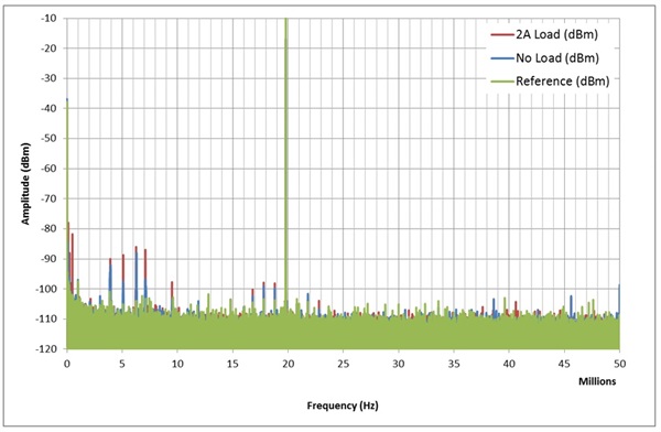
Let’s first establish a baseline for a loaded TPS54120 DC/DC converter. Figure 1 shows the fast Fourier transform (FFT) of the time-domain response represented as an amplitude in decibel milliwatt on the y-axis versus frequency on the x-axis.
 Figure 1 TPS54120 DC/DC Converter
Frequency Content versus Load
Figure 1 TPS54120 DC/DC Converter
Frequency Content versus LoadThe amplitude of the switching frequency is increasing in conjunction with the increased load. For example, going from no load to a 2A load, the 500kHz switching frequency power increases from -58dBm to -38dBm. The power present in the harmonics also rises. In the time domain, this will appear as an increase in peak-to-peak voltage.
Using the TPS54120 DC/DC converter at 1.8V followed by a π-filter into DVDD (while powering the AVDD with a TPS7A47 LDO voltage regulator), I compared the results to the reference FFT. The reference FFT is battery-powered, with one TPS7A47 regulator for each AVDD and DVDD, for two reasons: no additional load on the DC/DC converter and a 2A external load. See Figure 2.
 Figure 2 TPS54120 DC/DC with Ferrite on
DVDD Comparison
Figure 2 TPS54120 DC/DC with Ferrite on
DVDD ComparisonAs expected, the main degradation is at the switching frequency. The surprise is the 10dB degradation in the 4MHz to 8MHz band and the 5dB degradation around the 19.8MHz tone. This degradation – due to a poorer DVDD supply – has little dependency with the DC/DC converter load current.
Despite the high PSR of the ADS3444 on its DVDD supply, do not use a DC/DC converter here. Remember that the PSR measurement used a single sinewave with good phase noise, while the DC/DC converter has neither good phase noise nor good distortion. Figure 1 shows that the harmonic distortion terms of the DC/DC converter switching frequency are -20dBc for HD2, -30dBc for HD3, and -35dBc for HD4 and HD5. The combination of the switcher’s poor phase noise and the presence of harmonics on the switching frequency explains the new spurs appearing in the FFT, see Figure 3. These additional spurs are present despite a 32kHz low-pass filter set by the ferrite bead and the ADS3444’s local bypass capacitors.
 Figure 3 DVDD with Ferrite on DVDD
Comparison Details
Figure 3 DVDD with Ferrite on DVDD
Comparison DetailsLooking at the DC - 5MHz band, Figure 3, you can see that the PSR explanation I gave in my “Using a DC/DC converter to power an ADC” post was accurate. In that frequency band, the 2A load does bring higher spurs at the DC/DC switching frequency, in agreement with Figure 1.
Figure 4 shows the AVDD supply comparison.
The impact of the DC/DC converter with a simple π-filter on its output on the AVDD supply has some similarities to the DVDD supply, with spurs present at DC, the 4MHz to 8MHz band and around the signal tone.
Because the AVDD supply is more sensitive than the DVDD supply, the degradation occurring is not only more severe than with the DVDD, but also more severe as the load current on the DC/DC converter increases. The frequency band impacted is also more widespread, with noise tones appearing around 10MHz and 46MHz.
Filtering the undesirable noise tones generated by the DC/DC power supply is possible, but would require multiple π-filters on each supply, costing precious PCB area around the ADC.
 Figure 4 TPS54120 DC/DC with Ferrite on
AVDD Comparison DC to 5MHz Frequency Band Detail
Figure 4 TPS54120 DC/DC with Ferrite on
AVDD Comparison DC to 5MHz Frequency Band DetailFigure 4 shows the detail of the DC to 5MHz frequency band. The π-filter does a good job at attenuating both the thermal and ripple noise. However, this solution falls apart with increased load current. As a reminder, the reference FFT signal uses a battery with low-noise, high-PSRR LDOs (TPS7A47) for the AVDD and DVDD supplies.
 Figure 5 TPS54120 DC/DC with Ferrite on
AVDD Comparison, 15.6MHz to 23.8MHz Frequency Band Detail
Figure 5 TPS54120 DC/DC with Ferrite on
AVDD Comparison, 15.6MHz to 23.8MHz Frequency Band DetailFigure 5 shows the detail taken around the signal tone. Looking closely at the plot, each spur does not originate in the power supply, as they are all present in the reference measurement and do not correspond to the switching frequency of the DC/DC converter (~500kHz). Note that the poor phase noise and harmonic distortion of the DC/DC converter interacts with the ADC spurs.
No noise tones are present at ~500kHz around the 19.8MHz signal tone, indicating that the combination of π-filter and lower input signal (-17dBFS) is sufficient.
As I’ve shown in the first part of this series, using a DC/DC converter to power a high-performance pipeline converter will significantly degrade both SNR and spurious-free dynamic range (SFDR). In part 2, I will demonstrate proper post-filtering implementation of the DC/DC converter and compare the results to an ideal power supply.
In case you missed any other posts in this series, read my other blogs on creating a power supply for ADCs.