SSZTCK3 june 2015 LM10011 , TPS53355
The output voltage of a power supply is usually a fixed voltage, but sometimes it may be necessary to adjust that output voltage. For example, you may be able to reduce the power dissipation in a low-voltage high-current processor – while still keeping performance high – by adjusting the voltage fed to the core.
Adaptive Voltage Scaling (AVS) is a technology that provides this function and it’s becoming an increasingly popular feature of new processors. The “Adaptive Voltage Scaling Power Supply for Communication and Enterprise Storage ASIC Core Rails” TI Design reference design (PMP10488) is an example that would provide this functionality. Figure 1 shows the schematic for this design.
 Figure 1 Schematic
The TPS53355 is a synchronous buck converter with integrated field-effect transistors (FETs); it generates a 20A output power supply from a 12V source. The design uses TI’s DCAP™ IC technology for the output control. This control strategy is well suited to an AVS application because of the improved transient capabilities. The integrated FETs allow you to optimize performance inside the IC for improved efficiency and easy board layout. The output is adjustable from 0.67V to 0.95V.
The LM10011 voltage programmer controls the output voltage. This IC takes a four-bit digital signal from the processor and generates an analog current, which you can then inject into the feedback node in order to adjust the output voltage. Because the feedback voltage is fixed at the reference, the output voltage is adjustable according to Equation 1:
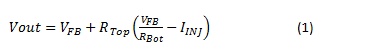
In this specific example, the output-voltage range you’ll need to control is from 0.67V to 0.95V. The LM10011 has a current-source output from 0 to 59.2µA.
Using the two extremes, you can write two equations and solve for both the high-side and low-side resistor values.
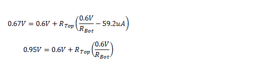
Taking into account tolerances and using 1% resistor values, RTop = 5.11K and RBot = 8.66K. These values give voltage set points of 0.954V and 0.652V.
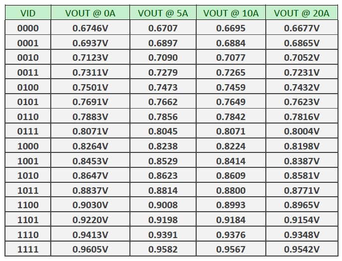
Table 1 lists measured data using the PMP10488 board.
|
Using AVS allows the processor to optimize the core voltage, thus improving performance and reducing power dissipation. This is just one example of how to create an adjustable-output power supply. For more information, see my latest Power Tips post on EETimes.
Additional Resources
Read the full Power Tips blog series