SSZTCS4 april 2015
Since its definition in 1983, RS-485 has become the preferred interface standard for many industrial fieldbus applications. In this RS-485 basics series on the new TI E2E Community Industrial Strength Blog, we hope to create present a useful, informative, and centralized resource for understanding the fundamentals of RS-485 and addressing common application questions that arise when designing RS-485 networks.
RS-485, formally known as American National Standards Institute (ANSI) Telecommunications Industry Association (TIA)/Electronic Industries Alliance (EIA)-485-A, is a balanced data transmission standard for serial communication. RS-485 allows for robust transmission of moderate data rates over long distances in multipoint communication applications, such as factory and building automation, motor control, and other field bus applications.
The RS-485 standard only specifies the electrical characteristics of drivers and receivers; it does not specify a protocol. Many higher-level interface standards reference RS-485 for their physical layer, such as Modicon bus (ModBus), process field bus (ProfiBus), DMX512 and others.
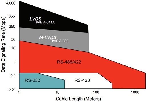
 Figure 1 Common Interface
Standards
Figure 1 Common Interface
StandardsFigure 1 shows the landscape of common interface standards arranged by data rate and distance. RS-485 improves noise immunity and extends the distance supported by RS-232 by implementing a differential, rather than single-ended, signaling technique. And while electrically similar, RS-485 extends RS-422 to allow for bidirectional communication.
Additionally, RS-485 allows for communication over greater distances than multipoint low-voltage differential signaling (M-LVDS) because of its larger signaling levels and wider common-mode range. However, for data rates higher than 20 megabits per second, M-LVDS becomes increasingly advantageous for its reduced power consumption relative to RS-485.
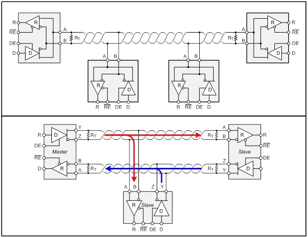
 Figure 2 Half- and Full-duplex
RS-485 Network Connections
Figure 2 Half- and Full-duplex
RS-485 Network ConnectionsRS-485 networks consist of multiple nodes connected in parallel to a bus. Figure 2 shows the typical network connections for half- and full-duplex RS-485 implementations. The majority of RS-485 applications implement half-duplex (two-wire) communication. Full-duplex communication requires two signal pairs (four-wire), and facilitates higher throughput by allowing nodes to transmit and receive data simultaneously. Modern transceiver designs allow hundreds of nodes to connect to the bus.
The next two installments in this series will discuss the basic design and operation of the RS-485 driver and receiver. We’ll also cover receiver failsafe operation, transceiver power dissipation, transient protection and more. If there are topics you would like us to address, please let us know in the comments section.
Additional Resources:
RS-422 and RS-485 Standards Overview and System Configurations, SLLA070D
Dual Isolated Half-Duplex RS-485 Repeater, TIDA-00333
Not all ESD specs cover the IEC ESD strike zone: Look for high IEC61000-4-2 coverage