SSZTCT8 april 2015 TPS65920
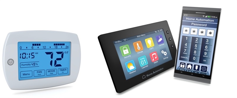
When designing an energy harvesting application such as smart meters, thermostats or smart-connected homes, there are several critical factors to consider. You must maximize efficiency, avoid any components that can cause board leakages, and use the power-saving mode to avoid power loss. Using power-saving modes is the best way to design the most efficient and least bulky system.
You don’t always need to use bigger batteries to produce the most efficient system. Most smart-home application boards include a microcontroller, transceiver and power amplifier (PA). You can design a system with smart devices, such as the TPS65290, ultra-low power management IC (PMIC), which enables you to select various power states when the system is operating under different load conditions without waking the processor or microcontroller. It also helps improve overall system efficiency, as shown in Figure 1. Integrated comparators help you continuously monitor the voltage rails and generate system interrupts to indicate an action.
 Figure 1 The TPS65290 Can Improve Overall System
Efficiency for Smart-home Applications
Figure 1 The TPS65290 Can Improve Overall System
Efficiency for Smart-home ApplicationsThe TPS65920 gives you the flexibility to power each block separately and the ability to change the output voltage of each rail. You can configure these options over I2C or the serial voltage identification (SVID) interface. During the active mode when the processor is on, the PMIC uses its buck converter to power the processor for maximum efficiency .. The device switches from buck to low dropout (LDO) to minimize the Iq loss if the system is not at full throttle. Then, when the system starts working for transmission, the buck-boost converter begins operating in buck-boost mode to power the PA. When the system is in a low-power state, all of the blocks are turned off to save power, but the minibuck stays in operation. Each block is designed to have peak efficiency at different loads.
Figure 2 shows the efficiency curve of the various blocks in the TPS65290. By enabling the right power block in the system’s various operation stages, you can significantly improve efficiency.
 Figure 2 The TPS65290’S Efficiency
Curve of Various Blocks Can Significantly Improve System Efficiency
Figure 2 The TPS65290’S Efficiency
Curve of Various Blocks Can Significantly Improve System EfficiencyWhich smart-home application you will power using the TPS65290?
Check out the Smart Cities blog series: