SWRU550A February 2019 – May 2019
5.1.4 Connecting the MMWAVEICBOOST
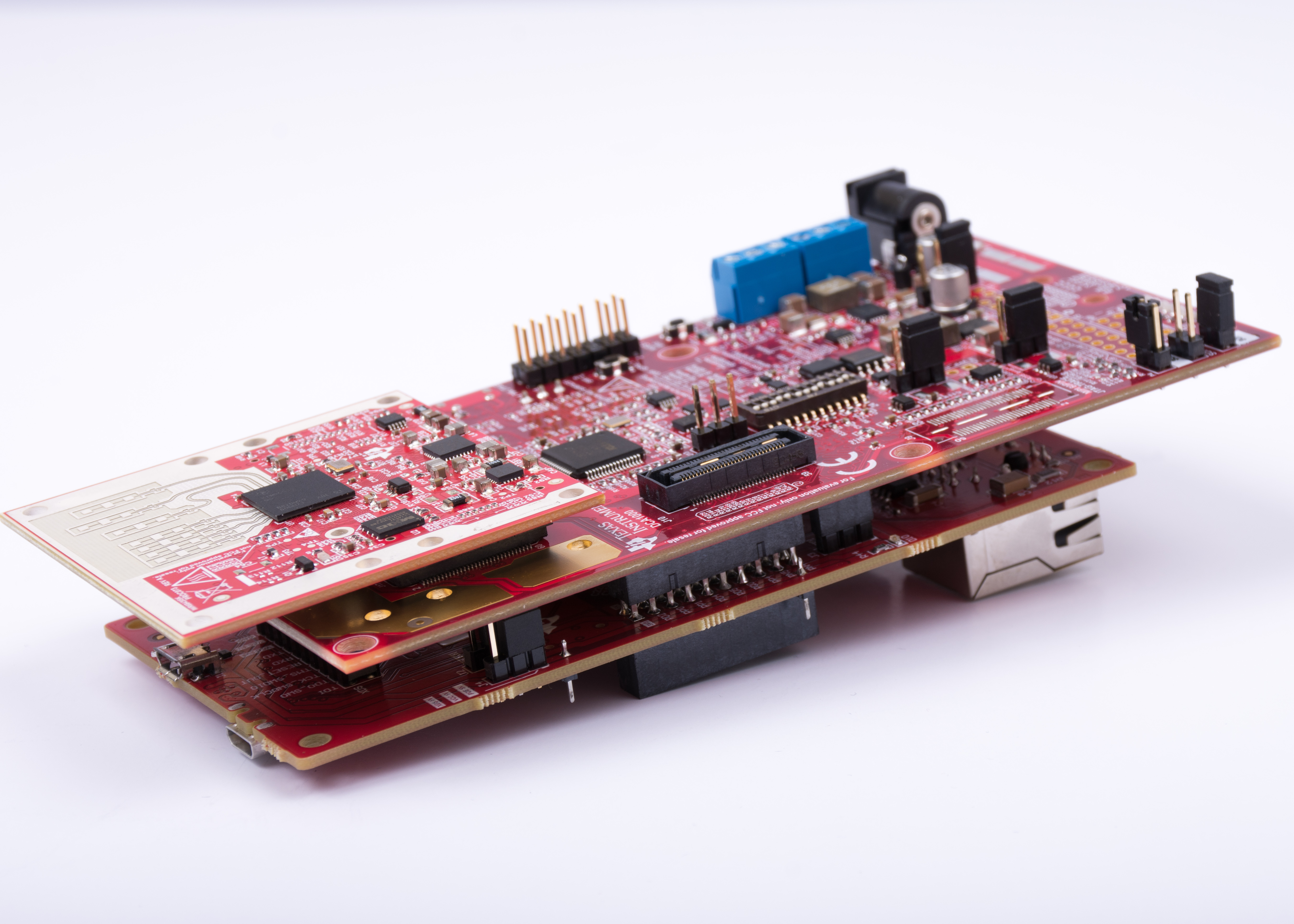
Mount the MMWAVEICBOOST on the MMWAVPOEEVM as shown in Figure 4 and ensure that MMWAVEPOEEVM is configured to source power through the RJ45 connector (J8).
 Figure 4. IWR6843ISK, MMWAVEICBOOST and MMWAVPOEEVM Board Stackup
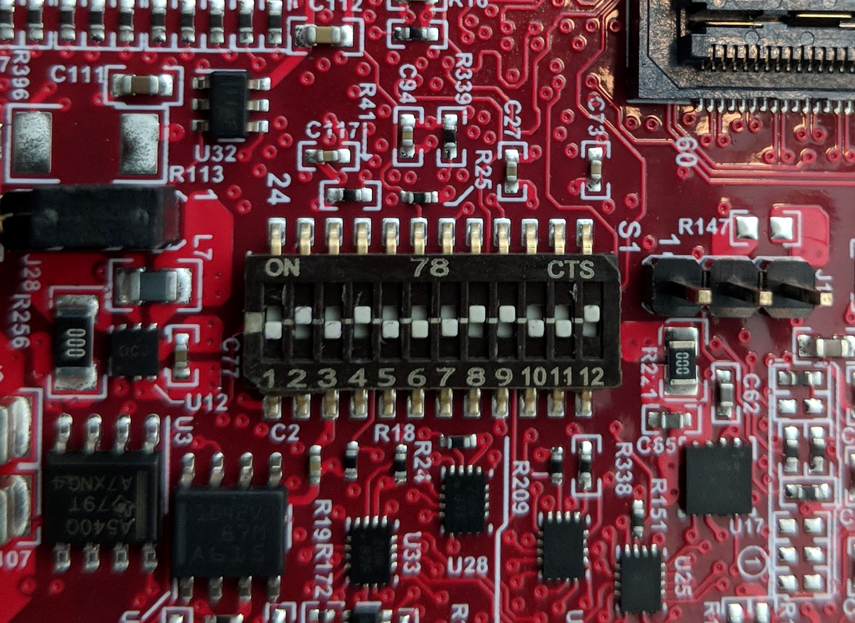
 Ensure the mux switches are configured as shown in Table 3.
Table 3. 40-Pin Header mux Switch Position
| Description | Switch Position |
|---|---|
| S1.1 | OFF |
| S1.2 | ON |
| S1.3 | OFF |
| S1.4 | ON |
| S1.5 | OFF |
| S1.6 | OFF |
| S1.7 | OFF |
| S1.8 | ON |
| S1.9 | ON |
| S1.10 | OFF |
| S1.11 | OFF |
| S1.12 | ON |
Ensure the shunt jumper is placed on the load switch header J28 and shown in Figure 5.
 Figure 5. MMWAVEICBOOST Switch S1 Configuration for POE Mode
 Connect the power sourcing equipment (PSE) to J8 (RJ45 jack) to power your application.