TIDT251A August   2022  – January 2023 TPS61288


  1.   Description
  2.   Features
  3.   Applications
  4. 1Test Prerequisites
    1. 1.1 Voltage and Current Requirements
    2. 1.2 Required Equipment
    3. 1.3 Dimensions
  5. 2Testing and Results
    1. 2.1 Efficiency Graphs
    2. 2.2 Efficiency Data
    3. 2.3 Thermal Images
  6. 3Waveforms
    1. 3.1 Switching
    2. 3.2 Output Voltage Ripple
    3. 3.3 Load Transients
    4. 3.4 Power On, Power Off

Switching

The waveforms of switching nodes at no-load and full-load conditions are shown in this section.

The waveforms in Figure 3-1 are the switching waveforms without a current-sharing circuit.

GUID-20211019-SS0I-HDXQ-BTWN-ZDXVDHTVGT6N-low.gifGUID-20211019-SS0I-J6XM-CCLR-HTBRS4VB1JN1-low.gifGUID-20211019-SS0I-7HFH-PL7M-X3HGNKFPFCD6-low.gif
Figure 3-1 Switching Waveforms Without Current Sharing

The waveforms in Figure 3-2 are the switching waveforms with an external amplifier current-sharing circuit.

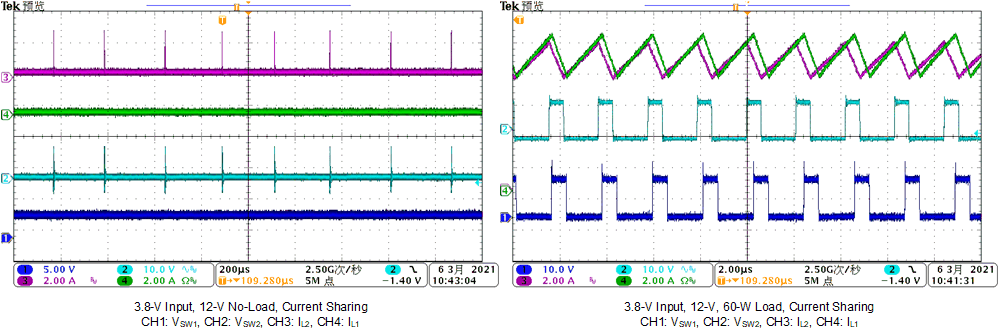
GUID-20211019-SS0I-KNRB-XVTG-WFHXM0VR73LL-low.gifGUID-20211019-SS0I-B2F0-KKDS-TNDTC7DCMV2W-low.gifGUID-20211019-SS0I-QJ6G-3K7B-LQKZ5MCJ5CGW-low.gif
Figure 3-2 Switching Waveforms With Current Sharing