TIDT292 June   2022


  1.   Description
  2.   Features
  3.   Applications
  4. 1Test Prerequisites
    1. 1.1 Voltage and Current Requirements
    2. 1.2 Required Equipment
    3. 1.3 Dimensions
    4. 1.4 Test Setup
  5. 2Testing and Results
    1. 2.1 Efficiency Graphs
    2. 2.2 Efficiency Data
    3. 2.3 Power Factor and iTHD Versus Load, VAC and Frequency
      1. 2.3.1 Power Factor and iTHD Tables
    4. 2.4 Thermal Image
    5. 2.5 Bode Plots
    6. 2.6 Input AC Current Measurements: Compliance to DO160 Harmonic Limits
  6. 3Waveforms
    1. 3.1 Switching
    2. 3.2 Output Voltage Ripple
    3. 3.3 AC Waveforms (Input Voltage and Current, PFC Output Voltage)
    4. 3.4 Load Transients
    5. 3.5 Inrush Current
    6. 3.6 Start-Up Sequence
    7. 3.7 Shutdown

Bode Plots

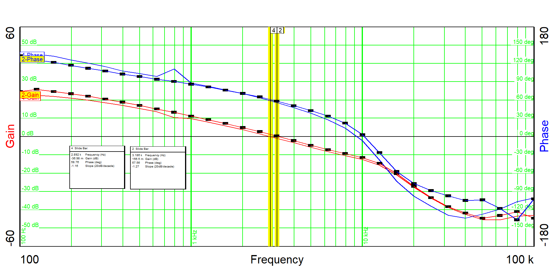
Figure 2-7 shows the bode plot of the converter, when supplied at 115 VAC, 400 Hz, while loaded at 5 A and 13 A. To measure the stability of the DC/DC stage, a 50-ā„¦ resistor was inserted in series to the common connection of R17 and R48 to the net ā€œ30Vā€.

GUID-20220530-SS0I-CZR4-LTZH-J1C6CVTP66XT-low.pngFigure 2-7 Bode Plot at 5 A and 13 A Load Current
Table 2-8 Crossover Frequency, Phase Margin and Gain Margin
Parameter IOUT = 5A IOUT = 13 A
Crossover frequency 3.186 kHz 2.892 kHz
Phase margin 57.56 degrees 58.76 degrees
Gain margin 11.67 dB 11.99 dB