TIDT359 October 2023
3.7 Watchdog
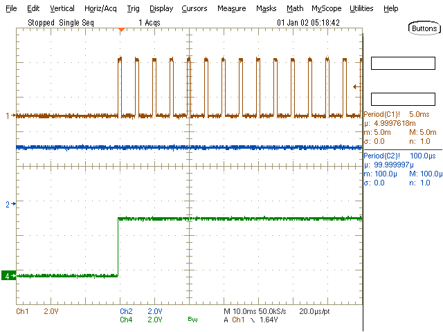
The watchdog timer behavior is shown in the following figures. The selected window watchdog is between 1.85 ms and 11.0 ms (typical values).

The watchdog is disabled (SET1 = LOW) until the first pulse on the input signal (WDI)
occurs. After that, the watchdog is enabled via the flip flop (SET1 = HIGH). The watchdog
does not output any errors since the WDI period is inside the allowed time window.
Figure 3-11 Watchdog at Start-Up (CH1: WDI at 5.0-ms
Period, CH2: WDO, CH4: SET1) 
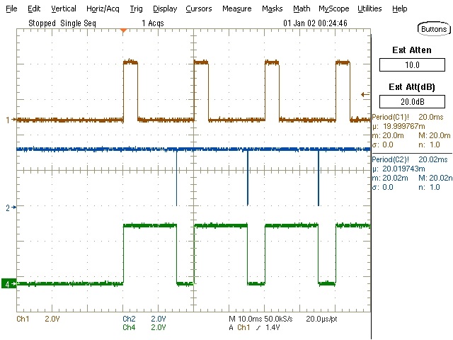
The watchdog is disabled (SET1 = LOW) until the first pulse on the input signal (WDI)
occurs. After that, the watchdog is enabled via the flip flop (SET1 = HIGH). The watchdog
outputs an error since the input signal period is outside the allowed time window. This
resets the flip flop (SET1 = LOW), and the cycle starts again.
Figure 3-12 Watchdog at Start-Up (CH1: WDI at 20.0-ms
Period, CH2: WDO, CH4: SET1)