TIDU800B March 2015 – December 2018
A.1 Field Oriented Control (FOC)
The FOC attempts to separately control the torque-producing and magnetizing flux components of the stator current. By decoupling control of the magnetization, the torque producing component of the stator flux becomes an independent torque control. To decouple the torque and flux, several mathematical transforms must be implemented. The FOC consists of controlling the stator currents represented by a vector. This control is based on projections which transforms a three-phase time- and speed-dependent system into a two co-ordinate (d and q co-ordinates) time-invariant system. Field-orientated controlled machines need two constants as input references: the torque component (aligned with the q co-ordinate) and the flux component (aligned with d co-ordinate).
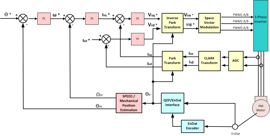
The first set of inputs to FOC are the motor phase currents. These measurements feed the Clarke transformation module. The outputs of this projection are designated Isα and Isβ. These two components of the current are the inputs of the Park transformation that gives the current in the d,q rotating reference frame. The Isd and Isq components are compared to the references Isd* (the flux reference) and Isq* (the torque reference). This control structure can control either PMSM or HVPM machines by changing the flux reference and obtaining rotor flux position. When controlling a PMSM, Isd* is set to zero. The torque command Isq* is the output of the speed regulator. The outputs of the current regulators are Vsd * and Vsq *. These are the inputs to the inverse Park transformation. The outputs of this transformation are Vsα * and Vsβ *, which are the components of the stator vector voltage in the α and β stationary orthogonal reference frame. These are the inputs of the Space Vector PWM. The outputs of the Space Vector PWM block are the signals that drive the inverter.
Both Park and inverse Park transformations need the rotor flux position. In a synchronous machine, the rotor speed is equal to the rotor flux speed. This is calculated from the rotor position of the QEP encoder. The rotor flux position (θ) is directly measured by position sensor or by integration of rotor speed. The rotor position permits the variable transformation from a stationary reference frame to a synchronously-rotating reference frame. As a result of the Park transformation, the q-axis current will control torque while d-axis current is forced to zero. The torque and flux decouple from each other. To view the overall block diagram of this project, see Figure 14.
 Figure 14. Block Diagram of Sensored Field Oriented Control