TIDUCU8A september 2022 – may 2023
3.3.4 Timing Tests
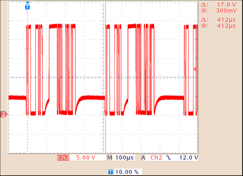
Further testing was done in terms of timing, especially on the capability of a cycle time of 400 µs and the timing jitter during this communication. For this test the BOOSTXL-IOLINKM-8 is combined with the AM243x LaunchPad, and the example from the MCU+ SDK is compiled and loaded. Figure 3-8 with infinite persistence shows a cycle time of about 412 µs and no visible jitter in this configuration.
 Figure 3-8 CQ Line Communication
Figure 3-9 shows the timing to be about 417 µs, well within the range allowed by the standard. Here also, the answer time of the connected device can be seen.
 Figure 3-9 Master Cycle Timing
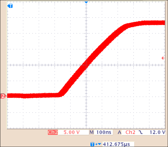
Figure 3-10 shows a zoomed in view of the second communication cycle on the CQ line. Trigger is set to trigger on one cycle and delay until the next one. This allows to look at the cycle to cycle jitter. With infinite persistence a jitter of about 50 ns gets visible. Compared to the rise and fall times, as well as the cycle timing, this is neglectable and does not degrade the system performance.
 Figure 3-10 Master Cycle Jitter