SLLA484A April 2020 – July 2022 ISO1044
1 Application Brief
Introduction
The Controller Area Network (CAN) bus standard has become widely adopted for a variety of applications since its initial development for the automotive market in the 1980’s. The key features of the protocol such as error detection, prioritization and arbitration that made CAN ideal for vehicles also presented advantages for industrial applications where safety and reliability are critical. CAN is now used across a variety of industrial applications such as elevators, escalators, building automation, grid infrastructure, factory automation, industrial transport and power delivery. As these applications trend toward higher performance and smaller solution sizes with each new generation, system designers face the challenge of shrinking their designs without compromising on performance.
Many of these applications involve communication between different voltage domains, requiring isolation of these CAN ports. Two other common reasons for isolating a CAN port in industrial applications are protection against ground potential differences (GPDs) between nodes or to improve electromagnetic compatibility (EMC). GPDs are caused when the distance between nodes becomes substantial or from common mode noise being coupled onto the CAN bus in noisy environments. These GPDs have the potential to cause data corruption and even damage to the transceiver itself. Adding galvanic isolation between the transceiver and MCU solves this problem as the high impedance of the isolation barrier protecting the sensitive MCU side circuitry, while allowing for reliable communication between the CAN transceiver and the MCU. Also, system designers can take advantage of the isolation barrier to improve EMC immunity of the overall system such as IEC ESD/EFT/Surge. For more details on this topic, refer to white paper: How to use isolation to improve ESD, EFT and surge immunity in industrial systems
Traditional Solution
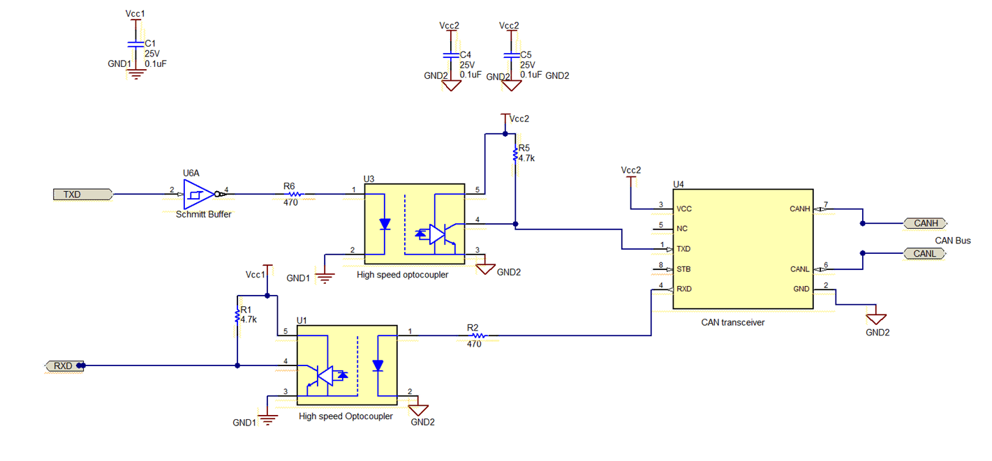
Historically, system designers have used optocouplers to create a discrete solution for isolating CAN nodes. This optocoupler-based approach shown in Figure 1-1 requires two high-speed optocouplers to transmit and receive data, a CAN transceiver, a Schmitt buffer to drive the LED of the transmit optocoupler, bypass capacitors and a few resistors for correct biasing.
 Figure 1-1 Optocoupler-based Solution for
an Isolated CAN Node
Figure 1-1 Optocoupler-based Solution for
an Isolated CAN NodeThe high number of external components needed for the optocoupler-based solution increases board space and can cause potential reliability concerns. Modern digital isolator solutions such as High-Voltage Isolation for Robust and Reliable System Operation provides a more reliable solution compared to the discrete optocoupler approach with lower failures in time (FIT) rates and a smaller overall solution size.
Integrated Isolated CAN
TI’s portfolio of isolated CAN transceivers integrates signal isolation and a transceiver in a single package to simplify the design process and further reduce board space compared to discrete solutions. The ISO1042 CAN Flexible Data Rate (FD) transceiver with +/-70-V bus fault protection offers 5-kVrms basic or reinforced isolation in a 16-DW and space saving 8-DWV package for high-voltage applications. For applications with lower isolation requirements, the ISO1044 provides a 3-kVrms isolation solution in an ultra-small 8-D package, making it ideal for breaking ground loops.
The ISO1044 supports +/-58-V bus fault protection to prevent potential damage to the device when the CAN bus shorts to 12-V or 24-V power supply lines. The device is also capable of CAN FD speeds of 5 Mbps with low loop delay of 225 ns maximum. The CAN standard ISO11898-2 asks for strict timing constraints on loop delay (time duration between transmit logic signal by MCU to the bus and back from bus to the receive logic data) and on pulse width distortions (in the transmit and receive path). Having the timing characteristics guaranteed in the data sheet of integrated devices, such as ISO1042 or ISO1044, eliminates the time and cost necessary to run additional simulations/testing on the timing specifications normally required for multi-device solutions due to the extra parasitics that exist in the interconnection path between isolation components and CAN transceiver. Both ISO1044 and ISO1042 offer wide input voltage ranges from 1.71 V to 5.5 V for the logic side power supply to interface directly with low-voltage microcontrollers and 4.5 V to 5.5 V for the bus-side power supply to remove the need for a tightly regulated bus-side supply in the system.
Reliability Comparison against Traditional Solutions
- Isolation Reliability:ISO1044 and ISO1042 are based on TI’s SiO2 based isolation technology. The high-voltage capacitors are constructed in a well-controlled semiconductor process and offer very low part-to-part variation. Also, the isolation barrier lifetime is well defined by the time dependent dielectric breakdown (TDDB) requirement per the VDE 0884-11 standard for non-optical isolators. On the other hand, optocouplers have manufacturing variability and no defined requirement in the standard to calculate lifetime of the device resulting in inconsistent performance, even in devices of the same wafer lot. A detailed explanation of lifetime reliability for TI’s SiO2 isolation technology can be found in the white paper Enabling high voltage signal isolation quality and reliability.
- Temperature Performance: Traditional optocouplers are rated up to 85°C max. There are optocouplers available in the market rated for 105°C, but they are rare and expensive. ISO1044 and ISO1042 are characterized and guaranteed over an extended industrial temperature range of –40 to 125°C. This extended temperature range enables high-power applications such as motor drives and solar inverters margin from the maximum ambient temperatures that can occur inside the equipment’s chassis.
- Transient Noise Performance: Optocouplers available in the market have typical common mode transient immunity (CMTI) specifications of 15 kV/us to 25 kV/us. This means if the noise between the two sides is varying faster than 15-25 kV/us, data communication across the isolation barrier may get corrupted. ISO1044 and ISO1042 provide typical CMTI of 100 kV/us. This is a direct measure of reliable data transmission and better noise immunity. In addition ISO1044 has robust bus side protection circuitry for HBM ESD and IEC ESD to meet +/-10 kV and +/-8 kV respectively without additional components.
Solution Size Comparison
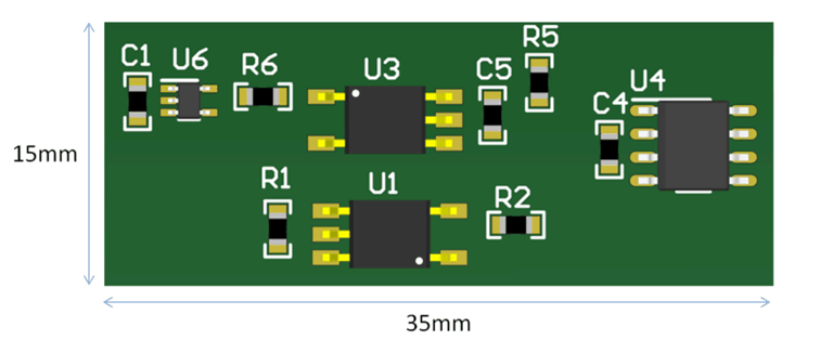
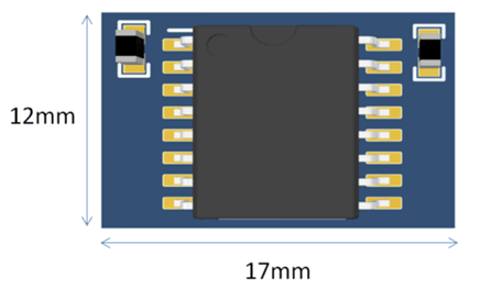
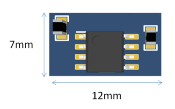
Figure 1-2 - Figure 1-4 below show the various implementations of creating an isolated CAN port. Figure 1-2 shows the layout for an optocoupler discrete solution, Figure 1-3 shows the industry standard 16-SOIC solution like the ISO1042, and Figure 1-4 shows the ISO1044 solution. The ISO1044 takes up only 84 mm2 and requires only two external ceramic bypass capacitors. The ISO1044 solution saves up to 84% board area compared to the optocoupler discrete solution and 60% compared to the industry standard 16-SOIC solution.
 Figure 1-2 Optocoupler Solution for
Isolating CAN Transceiver
 Figure 1-3 Industry Standard 16-SOIC
Isolated CAN Transceiver
 Figure 1-4 ISO1044 Isolated CAN
Transceiver
Figure 1-4 ISO1044 Isolated CAN
TransceiverConclusion
Many system designers are constantly tasked with adding more functionality and shrinking the form factor of each new generation without compromising the reliability of the system. The ISO1044 provides ultra-small size isolated CAN solution, ideal for breaking ground loops, that takes up a fraction of the board area as traditional 16-SOIC package or optocoupler discrete solutions. Using ISO1044 instead of the traditional solutions can free up board space to use for other sub-systems while increasing the reliability of the system.