SLLA556 June 2021 ISOS141-SEP , SN65C1168E-SEP
Application Brief
Design Goals
| Parameter | Design Requirement |
|---|---|
| Bit rate | 100kbps to 10Mbps |
| Bus length | 12M to 1500M |
| Maximum Total Ionizing Dose | 30krad(Si) |
| Maximum SEL to LET | 43MeV × cm2/mg |
| Isolation voltage | 3000VRMS per UL1577 |
Design Description
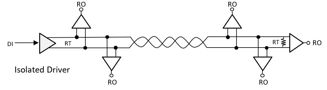
In spacecraft applications RS-422 might be used as a bus and payload telecommand and control interfaces. RS-422 was designed as serial communication methods to convey information between equipment by using balanced and differential twisted-pair cable. RS-422 is specified for multi-drop applications where only one driver connects up to 10 receivers through a single differential twisted bus. The following figure shows a typical half-duplex isolated RS-422 interface circuit.
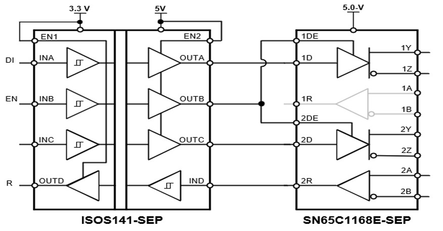
The following circuit uses the ISOS141-SEP digital isolator and SN65C1168E-SEP transceiver devices to achieve a space-grade isolated RS-422 driver.
Design Notes
The previous circuit uses the SN65C1168E-SEP driver to create an isolated RS-422 driver to isolate the primary device from the secondary devices. SN65C1168E-SEP consists of two receivers and can be used as secondary devices.
Design Steps
- Determine signaling rate versus cable length
RS-422 system can transmit up to 10Mbps, or over a 1500-m cable at a lower signaling rate. The signal rate is reciprocal to the cable length. Hence, it is important to figure out the maximum signal rate for a given cable length or vice versa. The following figure shows the RS-422 recommended signal rate over the cable length in its annex.
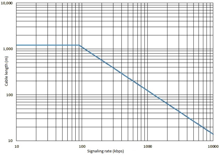
This system design uses a 1500-m cable. From the previous figure, the maximum recommended signal rate is 90kbps.
- Calculate the path delay
Path delay = Propagation delay of digital isolator + Propagation of RS-422 TX to bus + Propagation delay of wire
+ Propagation delay of bus to RS-422 RX Calculate bit timeParameter Conditions Typ (ns) MAX (ns) Propagation delay of ISOS-141-SEP With RL = 50Ω, CL = 15pF 10.7 16 Propagation delay of TX to bus With RL = 50Ω, CL = 40pF 8 16 Propagation delay of 1500-m wire Approximate delay is 5ns/m (Typ), 5.3ns/m (Max) 7500 7950 Propagation delay of bus to RX With RL = 50Ω, CL = 50pF 15 27 Path delay (Typ) = 10.7+8+7500+15 = 7534nsPath delay (Max) = 16+16+7950+127 = 8109ns - Calculate bit time
- Check path delay < bit time
- This design meets the timing
requirement as the approximate worst-case round-trip delay is 8109ns which is
less than 11100ns.
Note: If the path delay is greater than the bit time, the following options apply:
- Pick components with shorter propagation delays
- Shorten the cable length
- Lower the maximum signaling rate
- It is recommended to place a 120-Ω termination resistor at the other end from the driver.
Reference
| ISOS141-SEP | |
|---|---|
| VCC1, VCC2 | 2.25 V to 5.5 V |
| Data-rate | 10Mbps |
| Propagation delay | 10.7ns to 16ns |
| TID Characterized (ELDRS-Free) | 30krad(Si) |
| TID RLAT, RHA | 30krad(Si) |
| CMTI | ±100kV/µs |
| VISO | 3000 VRMS |
| http://www.ti.com/product/ISOS141-SEP | |
| SN65C1168E-SEP | |
|---|---|
| VCC1 | 4.5 V to 5.5 V |
| Data-rate | 1MHz |
| TID Characterized (ELDRS-Free) | 30krad(Si) |
| TID RLAT, RHA | 20krad(Si) |
| Common Mode Range | –7 V to 7 V |
| http://www.ti.com/product/SN65C1168E-SEP | |