SLVSAB4D June 2010 – January 2017 TPS61183
PRODUCTION DATA.
- 1 Features
- 2 Applications
- 3 Description
- 4 Revision History
- 5 Pin Configuration and Functions
- 6 Specifications
-
7 Detailed Description
- 7.1 Overview
- 7.2 Functional Block Diagram
- 7.3 Feature Description
- 7.4
Device Functional Modes
- 7.4.1 Brightness Dimming Control
- 7.4.2 Adjustable PWM Dimming Frequency and Mode Selection (R_FPWM/MODE)
- 7.4.3 Mode Selection - Programmable PWM Dimming or Direct PWM Dimming
- 7.4.4 Direct PWM Dimming
- 7.4.5 Overvoltage Clamp and Voltage Feedback (OVP/FB)
- 7.4.6 Current Sink Open Protection
- 7.4.7 Overcurrent and Short-Circuit Protection
- 7.4.8 Thermal Protection
- 7.4.9 Programmable PWM Dimming
- 8 Application and Implementation
- 9 Power Supply Recommendations
- 10Layout
- 11Device and Documentation Support
- 12Mechanical, Packaging, and Orderable Information
Package Options
Mechanical Data (Package|Pins)
- RTJ|20
Thermal pad, mechanical data (Package|Pins)
- RTJ|20
Orderable Information
1 Features
- 4.5-V to 24-V Input Voltage
- 38-V Maximum Output Voltage
- Integrated 2-A, 40-V MOSFET
- 280-kHz to 1-MHz Programmable Switching Frequency
- Adaptive Boost Output to WLED Voltages
- Wide PWM Dimming Frequency Range
- 100 Hz to 50 KHz for Direct PWM Mode
- 100 Hz to 22 KHz for Frequency Programmable Mode
- 100:1 Dimming Ratio at 20 kHz
- 10000:1 Dimming Ratio at 200 Hz (Direct PWM mode)
- Small External Components
- Integrated Loop Compensation
- Six Current Sinks of 30 mA, Maximum
- 1.5% (Typical) Current Matching
- PWM Brightness Interface Control
- PWM Programmable Mode Brightness Dimming Method or Direct PWM Dimming Method
- 4000-V HBM ESD Protection
- Programmable Overvoltage Threshold
- Built-in WLED Open and Short Protections
- Thermal Shutdown
2 Applications
3 Description
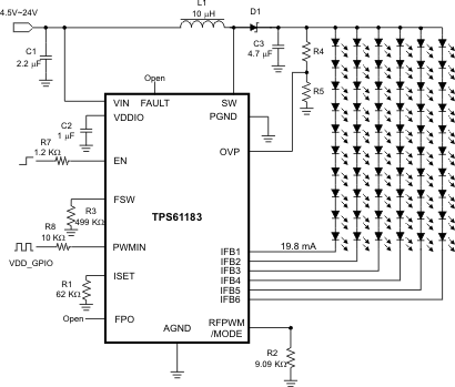
The TPS61183 device provides a highly integrated white-LED (WLED) driver solution for notebook LCD backlights. This device has a built-in high-efficiency boost regulator with integrated 2-A, 40-V power MOSFET. The six current sink regulators provide high-precision current regulation and matching. The device can support a total of up to 60 WLEDs. In addition, the boost output automatically adjusts its voltage to the WLED forward voltage to optimize efficiency.
The TPS61183 supports the programmable brightness dimming method. In this configuration, the dimming duty cycle of the WLED current is controlled by the input PWM signal but the dimming frequency is fixed and set by an external resistor. During direct PWM dimming, the WLED current completely synchronized with the input PWM signal's duty cycle and frequency.
Device Information(1)
| PART NUMBER | PACKAGE | BODY SIZE (NOM) |
|---|---|---|
| TPS61183 | QFN | 4.00 mm × 4.00 mm |
Typical Programmable PWM-Mode Application

4 Revision History
Changes from C Revision (October 2016) to D Revision
- Changed TPS61183 Layout drawing Go
Changes from B Revision (February 2012) to C Revision
- Deleted "For Notebooks" from title Go
- Changed "300 kHz" to "280 kHz" in FeaturesGo
- Added new "Applications" Go
- Added Device Information and Pin Configuration and Functions sections, ESD Ratings and Thermal Information tables, Feature Description, Device Functional Modes, Application and Implementation, Power Supply Recommendations, Layout, Device and Documentation Support, and Mechanical, Packaging, and Orderable Information sections; remove Ordering Information - see POAGo
- Changed "300 kHz" to "280 kHz" in Pin FunctionsGo
- Changed "300 kHz" to "280 kHz" in ROC table - 2 placesGo
- Changed "300 kHz" to "280 kHz"Go
Changes from A Revision (July 2010) to B Revision
Changes from * Revision (June 2010) to A Revision