SLUSA75B July 2010 – January 2020 BQ24650
PRODUCTION DATA.
- 1 Features
- 2 Applications
- 3 Description
- 4 Revision History
- 5 Description (continued)
- 6 Pin Configuration and Functions
- 7 Specifications
-
8 Detailed Description
- 8.1 Overview
- 8.2 Functional Block Diagram
- 8.3
Feature Description
- 8.3.1 Battery Voltage Regulation
- 8.3.2 Input Voltage Regulation
- 8.3.3 Battery Current Regulation
- 8.3.4 Battery Precharge
- 8.3.5 Charge Termination and Recharge
- 8.3.6 Power Up
- 8.3.7 Enable and Disable Charging
- 8.3.8 Automatic Internal Soft-Start Charger Current
- 8.3.9 Converter Operation
- 8.3.10 Synchronous and Non-Synchronous Operation
- 8.3.11 Cycle-by-Cycle Charge Undercurrent
- 8.3.12 Input Overvoltage Protection (ACOV)
- 8.3.13 Input Undervoltage Lockout (UVLO)
- 8.3.14 Battery Overvoltage Protection
- 8.3.15 Cycle-by-Cycle Charge Overcurrent Protection
- 8.3.16 Thermal Shutdown Protection
- 8.3.17 Temperature Qualification
- 8.3.18 Charge Enable
- 8.3.19 Inductor, Capacitor, and Sense Resistor Selection Guidelines
- 8.3.20 Charge Status Outputs
- 8.3.21 Battery Detection
- 8.4 Device Functional Modes
- 9 Application and Implementation
- 10Power Supply Recommendations
- 11Layout
- 12Device and Documentation Support
- 13Mechanical, Packaging, and Orderable Information
Package Options
Mechanical Data (Package|Pins)
- RVA|16
Thermal pad, mechanical data (Package|Pins)
- RVA|16
Orderable Information
8.3.21 Battery Detection
For applications with removable battery packs, the BQ24650 provides a battery absent detection scheme to reliably detect insertion or removal of battery packs.
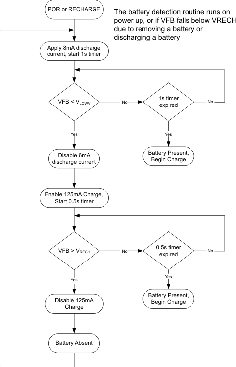
 Figure 12. Battery Detection Flowchart
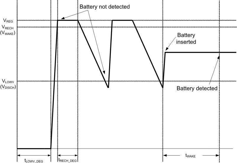
 When the device has powered up, a 6-mA discharge current is applied to the SRN terminal. If the battery voltage falls below the LOWV threshold within 1 second, the discharge source is turned off, and the charger is turned on at low charge current (125 mA). If the battery voltage gets up above the recharge threshold within 500 ms, there is no battery present and the cycle restarts. If either the 500 ms or 1 second timer time out before the respective thresholds are hit, a battery is detected and a charge cycle is initiated.
 Figure 13. Battery Detect Timing Diagram
 Take care that the total output capacitance at the battery node is not so large that the discharge current source cannot pull the VFB voltage below the LOWV threshold during the 1 second discharge time. The maximum output capacitance can be calculated according to Equation 9:

where
- CMAX is the maximum output capacitance,
- IDISCH is the discharge current,
- tDISCH is the discharge time,
- and R2 and R1 are the voltage feedback resistors from the battery to the VFB pin.
The 0.5 factor is the difference between the RECHARGE and the LOWV thresholds at the VFB pin.