DLPS140B March 2019 – May 2022 DLP2000
PRODUCTION DATA
- 1 Features
- 2 Applications
- 3 Description
- 4 Revision History
- 5 Pin Configuration and Functions
-
6 Specifications
- 6.1 Absolute Maximum Ratings
- 6.2 Storage Conditions
- 6.3 ESD Ratings
- 6.4 Recommended Operating Conditions
- 6.5 Thermal Information
- 6.6 Electrical Characteristics
- 6.7 Timing Requirements
- 6.8 System Mounting Interface Loads
- 6.9 Physical Characteristics of the Micromirror Array
- 6.10 Micromirror Array Optical Characteristics
- 6.11 Window Characteristics
- 6.12 Chipset Component Usage Specification
- 7 Detailed Description
- 8 Application and Implementation
- 9 Power Supply Recommendations
- 10Layout
- 11Device and Documentation Support
- 12Mechanical, Packaging, and Orderable Information
Package Options
Mechanical Data (Package|Pins)
- FQC|42
Thermal pad, mechanical data (Package|Pins)
Orderable Information
3 Description
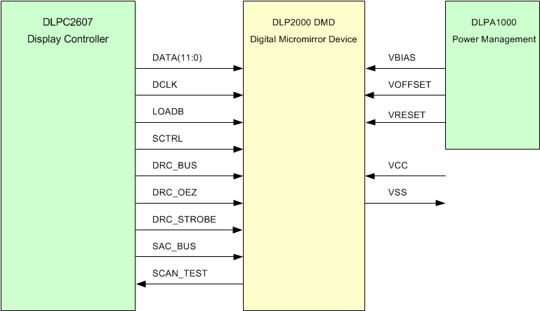
The DLP2000 digital micromirror device (DMD) is a digitally controlled micro-opto-electromechanical system (MOEMS) spatial light modulator (SLM). When coupled to an appropriate optical system, the DLP2000 DMD displays a crisp and high-quality image or video. DLP2000 is part of the chipset that comprises the DLP2000 DMD and DLPC2607 display controller. This chipset is also supported by the DLPA1000 PMIC/LED driver. The compact physical size of the DLP2000 is well-suited for portable equipment where a small form factor and low power is important. The compact package compliments the small size of LEDs to enable highly efficient, robust light engines.
Visit the getting started with TI DLP® Pico™ display technology page to learn how to get started with the DLP2000 DMD.
The DLP2000 includes established resources to help the user accelerate the design cycle, which include production ready optical modules, optical modules manufactures, and design houses.
| PART NUMBER | PACKAGE | BODY SIZE (NOM) |
|---|---|---|
| DLP2000 | FQC (42) | 14.12 mm × 4.97 mm |
 Simplified
Application