SLVSA06K October 2009 – January 2022 DRV8824
PRODUCTION DATA
- 1 Features
- 2 Applications
- 3 Description
- 4 Revision History
- 5 Pin Configuration and Functions
- 6 Specifications
- 7 Detailed Description
- 8 Application and Implementation
- 9 Layout
- 10Device and Documentation Support
- 11Mechanical, Packaging, and Orderable Information
Package Options
Refer to the PDF data sheet for device specific package drawings
Mechanical Data (Package|Pins)
- RHD|28
- PWP|28
Thermal pad, mechanical data (Package|Pins)
Orderable Information
8.2.2.1 Stepper Motor Speed
The first step in configuring the DRV8824 requires the desired motor speed and microstepping level. If the target application requires a constant speed, then a square wave with frequency ƒstep must be applied to the STEP pin.
If the target motor startup speed is too high, the motor will not spin. Make sure that the motor can support the target speed or implement an acceleration profile to bring the motor up to speed.
For a desired motor speed (v), microstepping level (nm), and motor full step angle (θstep),
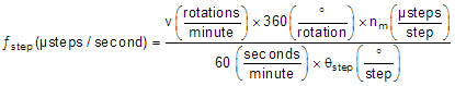
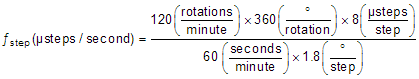
θstep can be found in the stepper motor data sheet or written on the motor itself.
For the DRV8824, the microstepping level is set by the MODE pins and can be any of the settings in Table 7-1. Higher microstepping will mean a smoother motor motion and less audible noise, but will increase switching losses and require a higher ƒstep to achieve the same motor speed.