SNIS161D March 2000 – January 2016 LM34
PRODUCTION DATA.
- 1 Features
- 2 Applications
- 3 Description
- 4 Revision History
- 5 Pin Configuration and Functions
- 6 Specifications
- 7 Detailed Description
- 8 Application and Implementation
- 9 Power Supply Recommendations
- 10Layout
- 11Device and Documentation Support
- 12Mechanical, Packaging, and Orderable Information
Package Options
Mechanical Data (Package|Pins)
Thermal pad, mechanical data (Package|Pins)
Orderable Information
6 Specifications
6.1 Absolute Maximum Ratings(1)(2)
over operating free-air temperature range (unless otherwise noted)| MIN | MAX | UNIT | ||
|---|---|---|---|---|
| Supply voltage | 35 | –0.2 | V | |
| Output voltage | 6 | –1 | V | |
| Output current | 10 | mA | ||
| Storage temperature, Tstg | TO-46 Package | −76 | 356 | °F |
| TO-92 Package | −76 | 300 | ||
| SO-8 Package | −65 | 150 | ||
(1) Stresses beyond those listed under Absolute Maximum Ratings may cause permanent damage to the device. These are stress ratings only, which do not imply functional operation of the device at these or any other conditions beyond those indicated under Recommended Operating Conditions. Exposure to absolute-maximum-rated conditions for extended periods may affect device reliability.
(2) If Military/Aerospace specified devices are required, contact the Texas Instruments Sales Office/ Distributors for availability and specifications.
6.2 ESD Ratings
| VALUE | UNIT | |||
|---|---|---|---|---|
| V(ESD) | Electrostatic discharge | Human-body model (HBM), per ANSI/ESDA/JEDEC JS-001(1) | ±2500 | V |
(1) JEDEC document JEP155 states that 500-V HBM allows safe manufacturing with a standard ESD control process.
6.3 Recommended Operating Conditions
over operating free-air temperature range (unless otherwise noted)| MIN | MAX | UNIT | ||
|---|---|---|---|---|
| Specified operating temperature range (TMIN ≤ TA ≤ TMAX) |
LM34, LM34A | –50 | 300 | °F |
| LM34C, LM34CA | –40 | 230 | ||
| LM34D | 32 | 212 | ||
| Supply Voltage Range (+VS) | 4 | 30 | V | |
6.4 Thermal Information
| THERMAL METRIC(1) | LM34 | UNIT | |||
|---|---|---|---|---|---|
| NDV (TO-46) | LP (TO-92) | D (SO8) | |||
| 3 PINS | 3 PINS | 8 PINS | |||
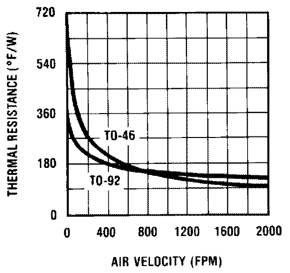
| RθJA | Junction-to-ambient thermal resistance | 720 | 324 | 400 | °F/W |
| RθJC | Junction-to-case thermal resistance | 43 | — | — | |
(1) For more information about traditional and new thermal metrics, see the IC Package Thermal Metrics application report, SPRA953.
6.5 Electrical Characteristics: LM34A and LM34CA
Unless otherwise noted, these specifications apply: −50°F ≤ TJ ≤ 300°F for the LM34 and LM34A; −40°F ≤ TJ ≤ 230°F for the LM34C and LM34CA; and 32°F ≤ TJ ≤ 212°F for the LM34D. VS = 5 Vdc and ILOAD = 50 µA in the circuit of Full-Range Fahrenheit Temperature Sensor; 6 Vdc for LM34 and LM34A for 230°F ≤ TJ ≤ 300°F. These specifications also apply from 5°F to TMAX in the circuit of Basic Fahrenheit Temperature Sensor (5°F to 300°F).| PARAMETER | TEST CONDITIONS | LM34A | LM34CA | UNIT | ||||||
|---|---|---|---|---|---|---|---|---|---|---|
| MIN | TYP | MAX | MIN | TYP | MAX | |||||
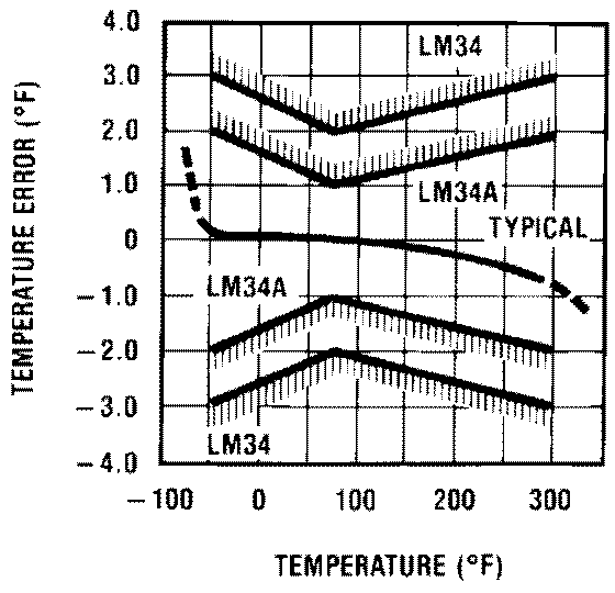
| Accuracy(3) | TA = 77°F | Tested Limit(1) | –1 | 1 | –1 | 1 | °F | |||
| Design Limit(2) | ||||||||||
| ±0.4 | ±0.4 | |||||||||
| T A = 0°F | Tested Limit | °F | ||||||||
| Design Limit | –2 | 2 | ||||||||
| ±0.6 | ±0.6 | |||||||||
| TA = TMAX | Tested Limit | –2 | 2 | –2 | 2 | °F | ||||
| Design Limit | ||||||||||
| ±0.8 | ±0.8 | |||||||||
| TA = TMIN | Tested Limit | –2 | 2 | °F | ||||||
| Design Limit | –3 | 3 | ||||||||
| ±0.8 | ±0.8 | |||||||||
| Nonlinearity (4) | Tested Limit | °F | ||||||||
| Design Limit | –0.7 | 0.7 | –0.6 | 0.6 | ||||||
| TA = 77°F | ±0.35 | ±0.3 | ||||||||
| Sensor gain (Average Slope) | Tested Limit | 9.9 | 10.1 | mV/°F | ||||||
| Design Limit | +9.9 | 10.1 | ||||||||
| TA = 77°F | +10 | 10 | ||||||||
| Load regulation(5) | TA = 77°F 0 ≤ IL ≤ 1 mA |
Tested Limit | –1 | 1 | –1 | 1 | mV/mA | |||
| Design Limit | ||||||||||
| ±0.4 | ±0.4 | |||||||||
| 0 ≤ IL ≤ 1 mA | Tested Limit | mV/mA | ||||||||
| Design Limit | –3 | 3 | –3 | 3 | ||||||
| ±0.5 | ±0.5 | |||||||||
| Line regulation(5) | TA = 77°F 5 V ≤ VS ≤ 30 V |
Tested Limit | –0.05 | 0.05 | –0.05 | 0.05 | mV/V | |||
| Design Limit | ||||||||||
| ±0.01 | ±0.01 | |||||||||
| 5 V ≤ VS ≤ 30 V | Tested Limit | mV/V | ||||||||
| Design Limit | –0.1 | 0.1 | –0.1 | 0.1 | ||||||
| ±0.02 | ±0.02 | |||||||||
| Quiescent current(6) | VS = 5 V, TA = 77°F | Tested Limit | 90 | 90 | µA | |||||
| Design Limit | ||||||||||
| 75 | 75 | |||||||||
| VS = 5 V | Tested Limit | µA | ||||||||
| Design Limit | 160 | 139 | ||||||||
| 131 | 116 | |||||||||
| VS = 30 V, TA = 77°F | Tested Limit | 92 | 92 | µA | ||||||
| Design Limit | ||||||||||
| 76 | 76 | |||||||||
| VS = 30 V | Tested Limit | µA | ||||||||
| Design Limit | 163 | 142 | ||||||||
| 132 | 117 | |||||||||
| Change of quiescent current(5) | 4 V ≤ VS ≤ 30 V, TA = 77°F | Tested Limit | 2 | 2 | µA | |||||
| Design Limit | ||||||||||
| 0.5 | 0.5 | |||||||||
| 5 V ≤ VS ≤ 30 V | Tested Limit | µA | ||||||||
| Design Limit | 3 | 3 | ||||||||
| 1 | 1 | |||||||||
| Temperature coefficient of quiescent current | Tested Limit | µA/°F | ||||||||
| Design Limit | 0.5 | 0.5 | ||||||||
| 0.3 | 0.3 | |||||||||
| Minimum temperature for rated accuracy | In circuit of Basic Fahrenheit Temperature Sensor (5°F to 300°F), IL = 0 TA = 77°F |
Tested Limit | °F | |||||||
| Design Limit | 5 | 5 | ||||||||
| 3 | 3 | |||||||||
| Long-term stability | TJ = TMAX for 1000 hours | ±0.16 | ±0.16 | °F | ||||||
(1) Tested limits are specified and 100% tested in production.
(2) Design limits are specified (but not 100% production tested) over the indicated temperature and supply voltage ranges. These limits are not used to calculate outgoing quality levels.
(3) Accuracy is defined as the error between the output voltage and 10 mV/°F times the device’s case temperature at specified conditions of voltage, current, and temperature (expressed in °F).
(4) Nonlinearity is defined as the deviation of the output-voltage-versus-temperature curve from the best-fit straight line over the rated temperature range of the device.
(5) Regulation is measured at constant junction temperature using pulse testing with a low duty cycle. Changes in output due to heating effects can be computed by multiplying the internal dissipation by the thermal resistance.
(6) Quiescent current is defined in the circuit of Basic Fahrenheit Temperature Sensor (5°F to 300°F).
6.6 Electrical Characteristics: LM34, LM34C, and LM34D
Unless otherwise noted, these specifications apply: −50°F ≤ TJ ≤ 300°F for the LM34 and LM34A; −40°F ≤ TJ ≤ 230°F for the LM34C and LM34CA; and +32°F ≤ TJ ≤ 212°F for the LM34D. VS = 5 Vdc and ILOAD = 50 µA in the circuit of Full-Range Fahrenheit Temperature Sensor; 6 Vdc for LM34 and LM34A for 230°F ≤ TJ ≤ 300°F. These specifications also apply from 5°F to TMAX in the circuit of Basic Fahrenheit Temperature Sensor (5°F to 300°F).| PARAMETER | CONDITIONS | LM34 | LM34C, LM34D | UNIT | ||||||
|---|---|---|---|---|---|---|---|---|---|---|
| MIN | TYP | MAX | MIN | TYP | MAX | |||||
| Accuracy, LM34, LM34C(3) | TA = 77°F | Tested Limit(1) | –2 | 2 | –2 | 2 | °F | |||
| Design Limit(2) | ||||||||||
| ±0.8 | ±0.8 | |||||||||
| TA = 0°F | Tested Limit | °F | ||||||||
| Design Limit | –3 | 3 | ||||||||
| ±1 | ±1 | |||||||||
| TA = TMAX | Tested Limit | –3 | 3 | °F | ||||||
| Design Limit | –3 | 3 | ||||||||
| ±1.6 | ±1.6 | |||||||||
| TA = TMIN | Tested Limit | °F | ||||||||
| Design Limit | –3 | 3 | –4 | 4 | ||||||
| ±1.6 | ±1.6 | |||||||||
| Accuracy, LM34D(3) | TA = 77°F | Tested Limit | –3 | 3 | °F | |||||
| Design Limit | ||||||||||
| ±1.2 | ||||||||||
| TA = TMAX | Tested Limit | °F | ||||||||
| Design Limit | –4 | 4 | ||||||||
| ±1.8 | ||||||||||
| TA = TMIN | Tested Limit | °F | ||||||||
| Design Limit | –4 | 4 | ||||||||
| ±1.8 | ||||||||||
| Nonlinearity (4) | Tested Limit | °F | ||||||||
| Design Limit | –1.0 | 1 | –1 | 1 | ||||||
| ±0.6 | ±0.4 | |||||||||
| Sensor gain (Average Slope) | Tested Limit | 9.8 | 10.2 | mV/°F | ||||||
| Design Limit | 9.8 | 10.2 | ||||||||
| 10 | 10 | |||||||||
| Load regulation(5) | TA = 77°F 0 ≤ IL ≤ 1 mA |
Tested Limit | –2.5 | 2.5 | –2.5 | 2.5 | mV/mA | |||
| Design Limit | ||||||||||
| ±0.4 | ±0.4 | |||||||||
| TMIN ≤ TA ≤ 150°F 0 ≤ IL ≤ 1 mA |
Tested Limit | mV/mA | ||||||||
| Design Limit | –6.0 | 6 | –6 | 6 | ||||||
| ±0.5 | ±0.5 | |||||||||
| Line regulation(5) | TA = 77°F, 5 V ≤ VS ≤ 30 V |
Tested Limit | –0.1 | 0.1 | –0.1 | 0.1 | mV/V | |||
| Design Limit | ||||||||||
| ±0.01 | ±0.01 | |||||||||
| 5 V ≤ VS ≤ 30 V | Tested Limit | mV/V | ||||||||
| Design Limit | –0.2 | 0.2 | –0.2 | 0.2 | ||||||
| ±0.02 | ±0.02 | |||||||||
| Quiescent current(6) | VS = 5 V, TA = 77°F | Tested Limit | 100 | 100 | µA | |||||
| Design Limit | ||||||||||
| 75 | 75 | |||||||||
| VS = 5 V | Tested Limit | µA | ||||||||
| Design Limit | 176 | 154 | ||||||||
| 131 | 116 | |||||||||
| VS = 30 V, TA = 77°F | Tested Limit | 103 | 103 | µA | ||||||
| Design Limit | ||||||||||
| 76 | 76 | |||||||||
| VS = 30 V | Tested Limit | µA | ||||||||
| Design Limit | 181 | 159 | ||||||||
| 132 | 117 | |||||||||
| Change of quiescent current(5) | 4 V ≤ VS ≤ 30 V, TA = +77°F |
Tested Limit | 3 | 3 | µA | |||||
| Design Limit | ||||||||||
| 0.5 | 0.5 | |||||||||
| 5 V ≤ VS ≤ 30 V | Tested Limit | µA | ||||||||
| Design Limit | 5 | 5 | ||||||||
| 1 | 1 | |||||||||
| Temperature coefficient of quiescent current | Tested Limit | µA/°F | ||||||||
| Design Limit | 0.7 | 0.7 | ||||||||
| 0.3 | 0.3 | |||||||||
| Minimum temperature for rated accuracy | In circuit of Basic Fahrenheit Temperature Sensor (5°F to 300°F), IL = 0 | Tested Limit | °F | |||||||
| Design Limit | 5.0 | 5 | ||||||||
| 3 | 3 | |||||||||
| Long-term stability | TJ = TMAX for 1000 hours | ±0.16 | ±0.16 | °F | ||||||
(1) Tested limits are specified and 100% tested in production.
(2) Design limits are specified (but not 100% production tested) over the indicated temperature and supply voltage ranges. These limits are not used to calculate outgoing quality levels.
(3) Accuracy is defined as the error between the output voltage and 10 mV/˚F times the device’s case temperature at specified conditions of voltage, current, and temperature (expressed in ˚F).
(4) Nonlinearity is defined as the deviation of the output-voltage-versus-temperature curve from the best-fit straight line over the rated temperature range of the device.
(5) Regulation is measured at constant junction temperature using pulse testing with a low duty cycle. Changes in output due to heating effects can be computed by multiplying the internal dissipation by the thermal resistance.
(6) Quiescent current is defined in the circuit of Basic Fahrenheit Temperature Sensor (5°F to 300°F).
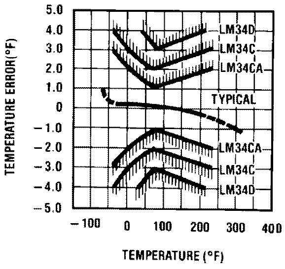
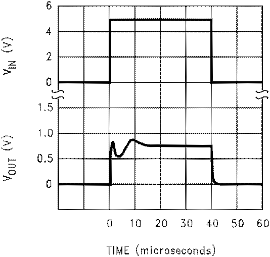
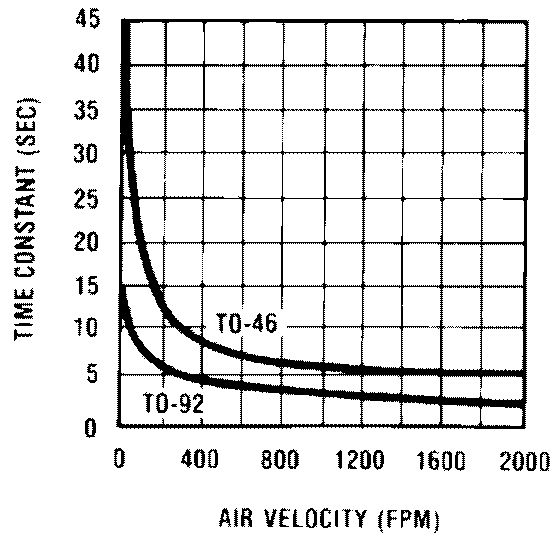
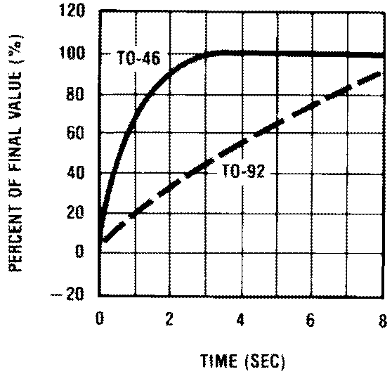
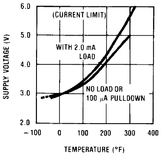
6.7 Typical Characteristics
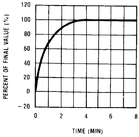
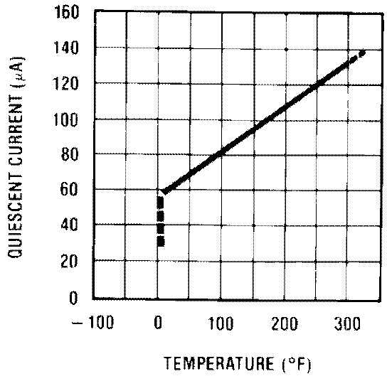
(in Circuit of Full-Range Fahrenheit Temperature Sensor; −VS = −5V, R1 = 100k)
