SLVS934C June 2009 – February 2021 TLC59025
PRODUCTION DATA
- 1 Features
- 2 Applications
- 3 Description
- 4 Revision History
- 5 Pin Configuration and Functions
-
6 Specifications
- 6.1 Absolute Maximum Ratings
- 6.2 ESD Ratings
- 6.3 Recommended Operating Conditions
- 6.4 Thermal Information
- 6.5 Electrical Characteristics for 3-V Input Voltage
- 6.6 Electrical Characteristics for 5.5-V Input Voltage
- 6.7 Power Dissipation Ratings
- 6.8 Timing Requirements
- 6.9 Switching Characteristics for 3-V Input Voltage
- 6.10 Switching Characteristics for 5.5-V Input Voltage
- 6.11 Typical Characteristics
- 7 Parameter Measurement Information
- 8 Detailed Description
- 9 Application and Implementation
- 10Power Supply Recommendations
- 11Layout
- 12Device and Documentation Support
- 13Mechanical, Packaging, and Orderable Information
Package Options
Mechanical Data (Package|Pins)
- DBQ|24
Thermal pad, mechanical data (Package|Pins)
Orderable Information
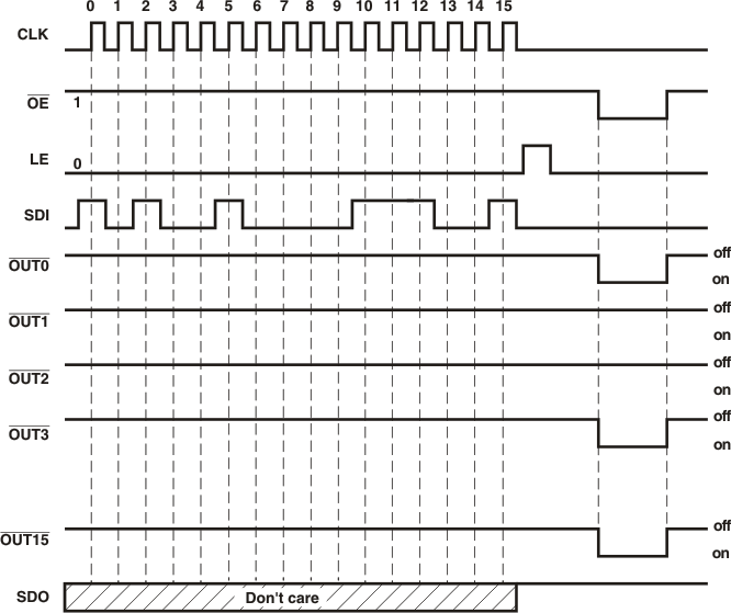
9.1.1 Turning on the LEDs
To turn on an LED connected to one of the outputs of the device, the output must be pulled low. To do this, the SDI signal must let the device know which outputs should be activated. Using the rising edge of CLK, the logic level of the SDI signal latches the desired state of each output into the shift register. Once this is complete, the LE signal must be toggled from low to high then back to low. Once /OE is pulled down, the corresponding outputs will be pulled low and the LEDs will be turned on. The below diagram shows outputs 0, 3, 4, 5, 10, 13, and 15 being activated.
 Figure 9-1 Timing Diagram