SLVSAA2D March 2010 – January 2016 TPS65182 , TPS65182B
PRODUCTION DATA.
- 1 Features
- 2 Applications
- 3 Description
- 4 Revision History
- 5 Pin Configuration and Functions
- 6 Specifications
-
7 Detailed Description
- 7.1 Overview
- 7.2 Functional Block Diagram
- 7.3
Feature Description
- 7.3.1 Modes of Operation
- 7.3.2 Mode Transistions
- 7.3.3 Wake-Up and Power Up Sequencing
- 7.3.4 Dependencies Between Rails
- 7.3.5 Soft-Start
- 7.3.6 VCOM Adjustment
- 7.3.7 VPOS and VNEG Supply Tracking
- 7.3.8 Fault Handling and Recovery
- 7.3.9 Power Good Pin
- 7.3.10 Panel Temperature Monitoring
- 7.3.11 NTC Bias Circuit
- 7.4 Device Functional Modes
- 7.5 Register Maps
- 8 Application and Implementation
- 9 Power Supply Recommendations
- 10Layout
- 11Device and Documentation Support
- 12Mechanical, Packaging, and Orderable Information
Package Options
Mechanical Data (Package|Pins)
- RGZ|48
Thermal pad, mechanical data (Package|Pins)
- RGZ|48
Orderable Information
7 Detailed Description
7.1 Overview
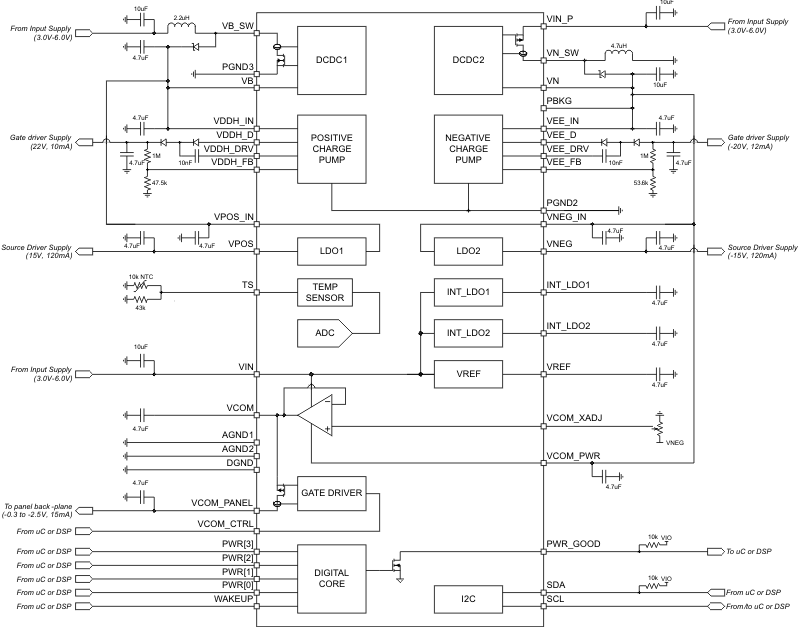
The TPS65182x family of devices provides two adjustable LDOs, inverting buck-boost converter, boost converter, thermistor monitoring, and flexible power-up and power-down sequencing. The system can be supplied by a regulated input voltage ranging from 3 V to 6 V. The device is characterized across a –10°C to 85°C temperature range, best suited for personal electronic applications.
The I2C interface provides comprehensive features for using the TPS65182x family of devices. All rails can be enabled or disabled. Power-up and power-down sequences can also be programmed through the I2C interface, as well as thermistor and interrupt configurations. Voltage adjustment can also be controlled through the I2C interface.
The adjustable LDOs can supply up to 120 mA of current. The default output voltages for each LDO can be adjusted through the I2C interface. LDO1 (VPOS) and LDO2 (VNEG) track each other in a way that they are of opposite sign, but same magnitude. The sum of VLDO1 and VLOD2 is guaranteed to be less than 50 mv.
There are two charge pumps: VDDH and VEE 10 mA and 12 mA respectively. These charge pumps boost the DC-DC boost converters ±16-V rails to provide a gate channel supply. The power good functionality is open-drain output, if any of the four power rails (CP1, CP2, LDO1, LDO2) are not in regulation, encounters a fault, or is disabled, the pin is pulled low. PWR_GOOD remains low if one of the rails is not enabled by the host, and only after all rails are in regulation, PWR_GOOD is released to HiZ state (pulled up by external resistor).
The TPS65182x family of devices provides circuitry to bias and measure an external NTC to monitor the display panel temperature in a range from –10°C to 85°C with an accuracy of ±1°C from 0°C to 50°C. Temperature measurements are triggered by the controlling host and the last temperature reading is always stored in the TMST_VALUE register. Interrupts are issued when the temperature exceeds the programmable HOT, or drops below the programmable COLD threshold, or when the temperature has changed by more than a user-defined threshold from the baseline value.
7.2 Functional Block Diagram

7.3 Feature Description
7.3.1 Modes of Operation
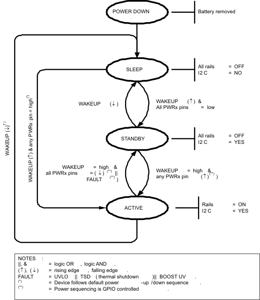
The TPS65182x has three modes of operation, SLEEP, STANDBY, and ACTIVE. SLEEP mode is the lowest-power mode in which all internal circuitry is turned off. In STANDBY, all power rails are shut down but the device is ready to accept commands through PWR[3:0] pins and/or I2C interface. In ACTIVE mode one or more power rails are enabled.
-
SLEEP
This is the lowest power mode of operation. All internal circuitry is turned off and the device does not respond to I2C communications. TPS65182x enters SLEEP mode whenever WAKEUP pin is pulled low.
-
STANDBY
In STANDBY all internal support circuitry is powered up and the device is ready to accept commands either through GPIO or I2C control but none of the power rails are enabled. To enter STANDBY mode the WAKEUP pin must be pulled high and all PWRx pins must be pulled low. The device also enters STANDBY mode if input under voltage lock out (UVLO), positive boost under voltage (VB_UV), or inverting buck-boost under voltage (VN_UV) is detected, or thermal shutdown occurs.
-
ACTIVE
The device is in ACTIVE mode when any of the output rails are enabled and no fault condition is present. This is the normal mode of operation while the device is powered up. In ACTIVE mode, a falling edge on any PWRx pin shuts down and a rising edge powers up the corresponding rail.
7.3.2 Mode Transistions
-
SLEEP → ACTIVE
WAKEUP pin is pulled high (rising edge) with any PWRx pin high. Rails come up in a pre-defined power-up sequence.
-
SLEEP → STANDBY
WAKEUP pin is pulled high (rising edge) with all PWRx pins low. Rails will remain down until one or more PWRx pin is pulled high.
-
ACTIVE → SLEEP
WAKEUP pin is pulled low (falling edge). Rails are shut down following the pre-defined power-down sequence.
-
ACTIVE → STANDBY
WAKEUP pin is high. All PWRx pins are pulled low (falling edge). Rails shut down in the order in which PWRx pins are pulled low. In the event of thermal shut down (TSD), under voltage lock out (UVLO), positive boost or inverting buck-boost under voltage (UV), the device shuts down all rails in a pre-defined power-down sequence.
-
STANDBY → ACTIVE
WAKEUP pin is high and any PWRx pin is pulled high (rising edge). Rails come up in the same order as PWRx pins are pulled high.
-
STANDBY → SLEEP
WAKEUP pin is pulled low (falling edge) while none of the output rails are enabled.
 Figure 3. Global State Diagram
7.3.3 Wake-Up and Power Up Sequencing
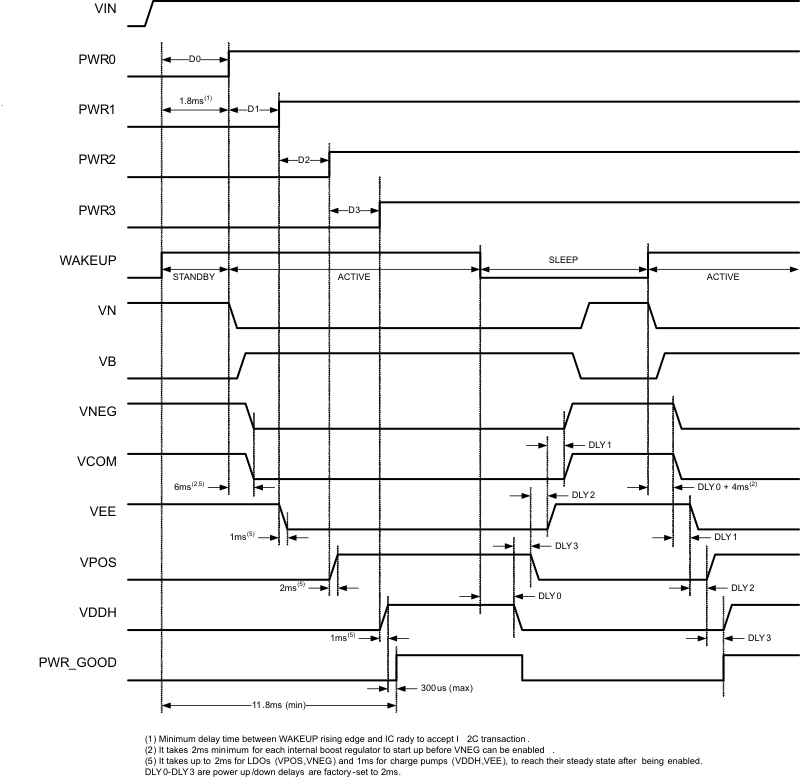
The TPS65182x supports a default power-up sequence supporting E Ink Vizplex displays. It also offers full user control of the power-up sequence through GPIO control using the PWR3, 2, 1, 0 pins. Using GPIO control, the output rails are enabled/disabled in the order in which the PWRx pins are asserted/de-asserted, respectively, and the power-up timing is controlled by the host only. Rails are in regulation 2 ms after their respective PWRx pin has been asserted with the exception of the first rail, which takes 6 ms to power up. The additional time is needed to power up the positive and inverting buck-boost regulator which need to be turned on before any other rail can be enabled. Once all rails are enabled and in regulation the PWR_GOOD pin is released (pin status = HiZ and power good line is pulled high by external pull-up resistor). The PWRx pins are assigned to the rails as follows:
- PWR0: LDO2 (VNEG) and VCOM
- PWR1: CP2 (VEE)
- PWR3: LDO2 (VPOS)
- PWR4: CP1 (VDDH)
Rails are powered down whenever the host de-asserts the respective PWRx pin, and once all rails are disabled the device enters STANDBY mode. The next step is then to de-assert the WAKEUP pin to enter SLEEP mode which is the lowest-power mode of operation.
It is possible for the host to force the TPS65182x directly into SLEEP mode from ACTIVE mode by de-asserting the WAKEUP pin in which case the device follows the pre-defined power-down sequence before entering SLEEP mode.
7.3.4 Dependencies Between Rails
Charge pumps, LDOs, and VCOM driver are dependent on the positive and inverting buck-boost converters and several dependencies exist that affect the power-up sequencing. These dependencies are listed below.
- Inverting buck-boost (DCDC2) must be in regulation before positive boost (DCDC1) can be enabled. Internally, DCDC1 enable is gated by DCDC2 power good.
- Positive boost (DCDC1) must be in regulation before LDO2 (VNEG) can be enabled. Internally LDO2 enable is gated DCDC1 power-good.
- Positive boost (DCDC1) must be in regulation before VCOM can be enabled; Internally VCOM enable is gated by DCDC1 power good.
- Positive boost (DCDC1) must be in regulation before negative charge pump (CP2) can be enabled. Internally CP2 enable is gated by DCDC1 power good.
- Positive boost (DCDC1) must be in regulation before positive charge pump (CP1) can be enabled. Internally CP1 enable is gated by DCDC1 power good.
- LDO2 must be in regulation before LDO1 can be enabled. Internally LDO1 enable is gated by LDO2 power good.
- The minimum delay time between any two PWRx pins must be > 62.5 µs in order to follow the power up sequence defined by GPIO control. If any two PWRx pins are pulled up together (< 62.5 µs apart) rails will be staggered in a manner that a subsequent rail’s enable is gated by PG of a preceding rail. In this case, the default order of power-up is LDO2 (VNEG), CP2 (VEE), LDO1 (VPOS), and CP1(VDDH). If any two PWRx pins are pulled low then all rails will go down at the same time.
 Figure 4. Power-Up and Power-Down Timing Diagram
7.3.5 Soft-Start
Softstart for DCDC1, DCDC2, LDO1, and LDO2 is accomplished by lowering the current limits during start-up. If DCDC1 or DCDC2 are unable to reach power-good status within 10 ms, the device enters STANDBY mode.
7.3.6 VCOM Adjustment
VCOM can be adjusted by an external potentiometer by connecting a potentiometer to the VCOM_XADJ pin. The potentiometer must be connected between ground and a negative supply. The gain from VCOM_XADJ to VCOM is 1 and therefore the voltage applied to VCOM_XADJ pin should range from -0.3 to -2.5V.
7.3.7 VPOS and VNEG Supply Tracking
LDO1 (VPOS) and LDO2 (VNEG) track each other in a way that they are of opposite sign but same magnitude. The sum of VLDO1 and VLOD2 is guaranteed to be < 50 mV.
7.3.8 Fault Handling and Recovery
The TPS65182x monitors input and output voltages and die temperature and will take action if operating conditions are outside normal limits. Whenever the TPS65182x encounters:
- Thermal Shutdown (TSD)
- Positive Boost Under Voltage (VB_UV)
- Inverting Buck-Boost Under Voltage (VN_UV)
- Input Under Voltage Lock Out (UVLO)
it will shut down all power rails and enter STANDBY mode. Shut down follows the pre-defined power-down sequence and once a fault is detected, the PWR_GOOD pin is pulled low.
Whenver the TPS65182x encounters under voltage on VNEG (VNEG_UV), VPOS (VPOS_UV), VEE (VEE_UV) or VDDH (VDDH_UV) it will shut down the corresponding rail (plus any dependent rail) only and remain in ACTIVE mode, allowing the DCDC converters to remain up. Again, the PWR_GOOD pin will be pulled low.
As the PWRx inputs are edge sensitive, the host must toggle the PWRx pins to re-enable the rails through GPIO control, i.e. it must bring the PWRx pins low before asserting them again.
7.3.9 Power Good Pin
The power good pin (PWR_GOOD) is an open drain output that is pulled high when all four power rails (CP1, CP2, LDO1, LDO2) are in regulation and is pulled low if any of the rails encounters a fault. PWR_GOOD remains low if one of the rails is not enabled by the host and only after all rails are in regulation PWR_GOOD is released to HiZ state (pulled up by external resistor).
7.3.10 Panel Temperature Monitoring
The TPS65182x provides circuitry to bias and measure an external negative temperature coefficient resistor (NTC) to monitor device temperature in a range from –10°C to 85°C with and accuracy of ±1°C from 0°C to 50°C. Temperature reading is automatically updated every 60 s.
7.3.11 NTC Bias Circuit
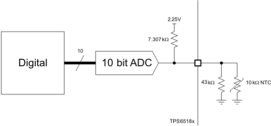
Figure 5 below shows the block diagram of the NTC bias and measurement circuit. The NTC is biased from an internally generated 2.25-V reference voltage through an integrated 7.307-KΩ bias resistor. A 43-KΩ resistor is connected parallel to the NTC to linearize the temperature response curve. The circuit is designed to work with a nominal 10-KΩ NTC and achieves accuracy of ±1°C from 0°C to 50°C. The voltage drop across the NTC is digitized by a 10-bit SAR ADC and translated into an 8-bit two’s complement by digital per Table 1.
Table 1. ADC Output Value vs Termperature
| TEMPERATURE | TMST_VALUE[7:0] |
|---|---|
| < -10°C | 1111 0110 |
| -10°C | 1111 0110 |
| -9°C | 1111 0111 |
| ... | ... |
| -2°C | 1111 1110 |
| -1°C | 1111 1111 |
| 0°C | 0000 0000 |
| 1°C | 0000 0001 |
| 2°C | 0000 0010 |
| ... | ... |
| 25°C | 0001 1001 |
| ... | |
| 85°C | 0101 0101 |
| > 85°C | 0101 0101 |
 Figure 5. NTC Bias and Measurement Circuit
7.4 Device Functional Modes
7.4.1 I2C Bus Operation
The TPS65182x supports a special I2C mode making it compatible with the EPSON® Broadsheet S1D13521 timing controller. Standard I2C protocol requires the following steps to read data from a register:
- Send device slave address, R/nW bit set low (write command)
- Send register address
- Send device slave address, R/nW set high (read command)
- The slave will respond with data from the specified register address.end device slave address, R/nW set high (read command).
The EPSON® Broadsheet S1D13521 controller does not support I2C writes nor I2C reads from addressed registers, therefore the TPS65182x I2C interface has been modified and the reading the temperature data is reduced to two steps:
- Send device address, R/nW set high (read command)
- Read the data from the slave. The slave will respond with data from TMST_VALUE register address.
 Figure 6. Subaddress in I2C Transmission
The I2C Bus is a communications link between a controller and a series of slave terminals. The link is established using a two-wired bus consisting of a serial clock signal (SCL) and a serial data signal (SDA). The serial clock is sourced from the controller in all cases where the serial data line is bi-directional for data communication between the controller and the slave terminals. Each device has an open Drain output to transmit data on the serial data line. An external pull-up resistor must be placed on the serial data line to pull the drain output high during data transmission.
Data transmission is initiated with a start bit from the controller as shown in Figure 7. The start condition is recognized when the SDA line transitions from high to low during the high portion of the SCL signal. Upon reception of a start bit, the device will receive serial data on the SDA input and check for valid address and control information. If the appropriate group and address bits are set for the device, then the device will issue an acknowledge pulse and prepare the receive subaddress data. Subaddress data is decoded and responded to as per the Register Map section of this document. Data transmission is completed by either the reception of a stop condition or the reception of the data word sent to the device. A stop condition is recognized as a low to high transition of the SDA input during the high portion of the SCL signal. All other transitions of the SDA line must occur during the low portion of the SCL signal. An acknowledge is issued after the reception of valid address, sub-address and data words. Reference Figure 7.
 Figure 7. I2C Start/Stop/Acknowledge Protocol
 Figure 8. I2C Data Transmission Timing
7.5 Register Maps
Table 2. Register Address Map
| REGISTER | ADDRESS (HEX) | NAME | DEFAULT VALUE |
DESCRIPTION |
|---|---|---|---|---|
| 0 | 0x00 | TMST_VALUE | N/A | Thermistor value read by ADC |
7.5.1 Thermistor Readout (TMST_VALUE) Register (offset = 0x00h)
| DATA BIT | D7 | D6 | D5 | D4 | D3 | D2 | D1 | D0 |
|---|---|---|---|---|---|---|---|---|
| FIELD NAME | TMST_VALUE[7:0] | |||||||
| READ/WRITE | R | R | R | R | R | R | R | R |
| RESET VALUE | N/A | N/A | N/A | N/A | N/A | N/A | N/A | N/A |
| FIELD NAME | BIT DEFINITION |
|---|---|
| TMST_VALUE[7:0] | Temperature read-out |
| 1111 0110 – < -10°C | |
| 1111 0110 – -10°C | |
| 1111 0111 – -9°C | |
| ... | |
| 1111 1110 – -2°C | |
| 1111 1111 – -1 °C | |
| 0000 0000 – 0 °C | |
| 0000 0001 – 1°C | |
| 0000 0010 – 2°C | |
| ... | |
| 0001 1001 – 25°C | |
| ... | |
| 0101 0101 – 85°C | |
| 0101 0101 – > 85°C |