JAJSCL7B December   2015  – December 2021 INA300-Q1

PRODUCTION DATA  

  1. 特長
  2. アプリケーション
  3. 概要
  4. Revision History
  5. Pin Configuration and Functions
  6. Specifications
    1. 6.1 Absolute Maximum Ratings
    2. 6.2 ESD Ratings
    3. 6.3 Recommended Operating Conditions
    4. 6.4 Thermal Information
    5. 6.5 Electrical Characteristics
    6. 6.6 Timing Requirements
    7. 6.7 Typical Characteristics
  7. Detailed Description
    1. 7.1 Overview
    2. 7.2 Functional Block Diagram
    3. 7.3 Feature Description
      1. 7.3.1 Selecting a Current-Sensing Resistor
        1. 7.3.1.1 Selecting a Current-Sensing Resistor: Example
      2. 7.3.2 Setting The Current-Limit Threshold
        1. 7.3.2.1 Resistor-Controlled Current Limit
        2. 7.3.2.2 Voltage Source-Controlled Current Limit
      3. 7.3.3 Delay Setting
      4. 7.3.4 Alert Timing Response
      5. 7.3.5 Selectable Hysteresis
      6. 7.3.6 Alert Output
      7. 7.3.7 Noise Adjustment Factor (NAF)
    4. 7.4 Device Functional Modes
      1. 7.4.1 Alert Mode
        1. 7.4.1.1 Transparent Output Mode
        2. 7.4.1.2 Latch Output Mode
      2. 7.4.2 Disable Mode
      3. 7.4.3 Input Filtering
      4. 7.4.4 Using the INA300-Q1 INA300-Q1 With Common-Mode Transients Above 36 V
  8. Application and Implementation
    1. 8.1 Application Information
    2. 8.2 Typical Applications
      1. 8.2.1 Unidirectional Operation
        1. 8.2.1.1 Design Requirements
        2. 8.2.1.2 Detailed Design Procedure
        3. 8.2.1.3 Application Curve
      2. 8.2.2 Bidirectional Operation
        1. 8.2.2.1 Design Requirements
        2. 8.2.2.2 Detailed Design Procedure
        3. 8.2.2.3 Application Curve
      3. 8.2.3 Window Comparator
        1. 8.2.3.1 Design Requirements
        2. 8.2.3.2 Detailed Design Procedure
        3. 8.2.3.3 Application Curve
  9. Power Supply Recommendations
  10. 10Layout
    1. 10.1 Layout Guidelines
    2. 10.2 Layout Example
  11. 11Device and Documentation Support
    1. 11.1 Documentation Support
      1. 11.1.1 Related Documentation
    2. 11.2 Receiving Notification of Documentation Updates
    3. 11.3 サポート・リソース
    4. 11.4 Trademarks
    5. 11.5 Electrostatic Discharge Caution
    6. 11.6 Glossary
  12. 12Mechanical, Packaging, and Orderable Information

パッケージ・オプション

メカニカル・データ(パッケージ|ピン)
サーマルパッド・メカニカル・データ
発注情報

概要

INA300-Q1 は、電流センシング (シャント) 抵抗の両端に発生する電圧を測定することで過電流状態を検出する、同相電圧範囲の広い電流センシング・コンパレータです。このデバイスは、電源電圧にかかわらず、0V~36V の同相電圧で差動電圧信号を測定できます。INA300-Q1 デバイスは、外付けの制限設定抵抗 1 つで、スレッショルド範囲を設定できます。ヒステリシスを選択できるため、0mV~250mV の広い入力信号範囲に合わせてコンパレータの動作を調整できます。

デバイスにはオープン・ドレインのアラート出力があり、透過モード (出力ステータスが入力状態に従う) またはラッチ・モード (ラッチがクリアされたときにアラート出力がクリアされる) で動作するよう構成できます。デバイスの応答時間を選択可能なため、過電流アラートは最短では 10µs で発行できます。

INA300-Q1 デバイスは 2.7V~5.5V の単一電源で動作し、最大消費電流は 135µA です。INA300-Q1 デバイスは拡張動作温度範囲の –40℃~+125℃で動作が規定されており、VSSOP-10 パッケージで供給されます。

製品情報
部品番号 パッケージ(1) 本体サイズ (公称)
INA300-Q1 VSSOP (10) 3.00mm × 3.00mm
利用可能なすべてのパッケージについては、データシートの末尾にあるパッケージ・オプションについての付録を参照してください。
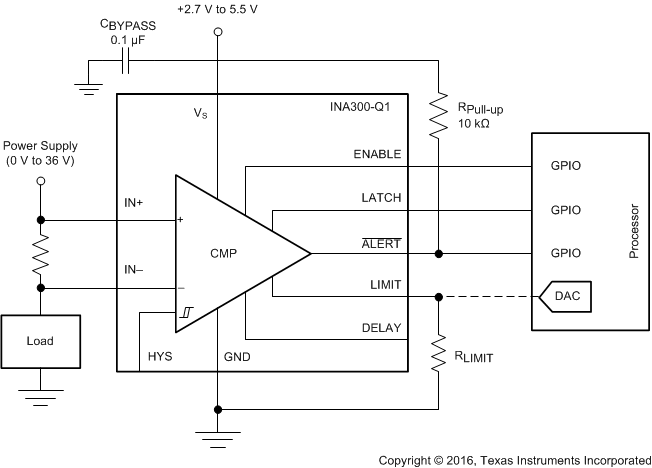
GUID-BB34A7EE-2EC3-4E73-A77A-863EB452AF65-low.gif 代表的なアプリケーション回路図