SLVS029H January 1984 – November 2015 TL499A
PRODUCTION DATA.
- 1 Features
- 2 Applications
- 3 Description
- 4 Revision History
- 5 Pin Configuration and Functions
- 6 Specifications
- 7 Detailed Description
- 8 Application and Implementation
- 9 Power Supply Recommendations
- 10Layout
- 11Device and Documentation Support
- 12Mechanical, Packaging, and Orderable Information
パッケージ・オプション
デバイスごとのパッケージ図は、PDF版データシートをご参照ください。
メカニカル・データ(パッケージ|ピン)
- P|8
- PS|8
サーマルパッド・メカニカル・データ
発注情報
8 Application and Implementation
NOTE
Information in the following applications sections is not part of the TI component specification, and TI does not warrant its accuracy or completeness. TI’s customers are responsible for determining suitability of components for their purposes. Customers should validate and test their design implementation to confirm system functionality.
8.1 Application Information
One or two power sources will be regulated to an output voltage set by two feedback resistors.
8.2 Typical Application
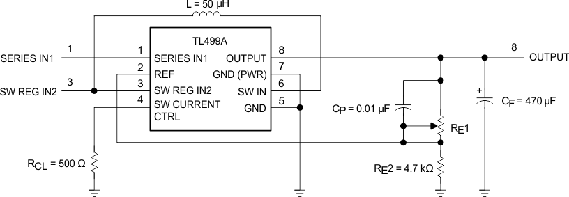
Figure 3 shows the basic configuration of the two power source voltage regulator
 Figure 3. TL499A Basic Configuration
8.2.1 Design Requirements
Provide one or more of the following power sources:
- SERIES IN1 voltage greater than OUTPUT voltage by more than dropout voltage
- SW REG IN2 voltage less than OUTPUT voltage
Select RCL value based on Table 1 through Table 5.
Table 1. Maximum Output Current vs Input and Output Voltages for Step-Up Switching Regulator With RCL = 150 Ω
| OUTPUT VOLTAGE (V) | SWITCHING REGULATOR INPUT VOLTAGE (SW REG IN2) (V) | ||||||||||||
|---|---|---|---|---|---|---|---|---|---|---|---|---|---|
| 1.1 | 1.2 | 1.3 | 1.5 | 1.7 | 2 | 2.5 | 3 | 5 | 6 | 9 | |||
| OUTPUT CURRENT (mA) | |||||||||||||
| 30 | 65 | 90 | |||||||||||
| 25 | 50 | 80 | 100 | ||||||||||
| 20 | 20 | 25 | 30 | 85 | 100 | 100 | |||||||
| 15 | 15 | 20 | 30 | 45 | 55 | 100 | 100 | 100 | |||||
| 12 | 10 | 15 | 20 | 25 | 30 | 40 | 55 | 70 | 100 | 100 | 100 | ||
| 10 | 15 | 20 | 25 | 30 | 35 | 45 | 65 | 80 | 100 | 100 | |||
| 9 | 20 | 25 | 25 | 35 | 40 | 50 | 70 | 90 | 100 | 100 | |||
| 6 | 30 | 35 | 40 | 45 | 55 | 75 | 95 | 100 | |||||
| 5 | 35 | 40 | 45 | 55 | 70 | 85 | 100 | 100 | Circuit of Figure 1, except: RCL = 150 Ω CF = 330 μF CP = 0.1 μF |
||||
| 4.5 | 35 | 45 | 50 | 60 | 75 | 95 | 100 | 100(1) | |||||
| 3 | 55 | 65(1) | 75(1) | 95(1) | 100(1) | ||||||||
| 2.9 | 60(1) | 70(1) | 75(1) | 100(1) | 100(1) | ||||||||
Table 2. Maximum Output Current vs Input and Output Voltages for Step-Up Switching Regulator With RCL = 200 Ω
| OUTPUT VOLTAGE (V) | SWITCHING REGULATOR INPUT VOLTAGE (SW REG IN2) (V) | ||||||||||||
|---|---|---|---|---|---|---|---|---|---|---|---|---|---|
| 1.1 | 1.2 | 1.3 | 1.5 | 1.7 | 2 | 2.5 | 3 | 5 | 6 | 9 | |||
| OUTPUT CURRENT (mA) | |||||||||||||
| 30 | 50 | 100 | |||||||||||
| 25 | 50 | 70 | 100 | ||||||||||
| 20 | 15 | 25 | 30 | 70 | 90 | 100 | |||||||
| 15 | 10 | 15 | 25 | 35 | 45 | 90 | 100 | 100 | |||||
| 12 | 10 | 10 | 15 | 20 | 25 | 35 | 45 | 60 | 100 | 100 | 100 | ||
| 10 | 15 | 20 | 20 | 25 | 30 | 40 | 55 | 70 | 100 | 100 | |||
| 9 | 20 | 20 | 25 | 30 | 35 | 45 | 60 | 80 | 100 | ||||
| 6 | 25 | 30 | 35 | 45 | 50 | 65 | 90 | 100 | |||||
| 5 | 30 | 35 | 40 | 55 | 60 | 75 | 100 | 100 | Circuit of Figure 1, except: RCL = 200 Ω CF = 330 μF CP = 0.1 μF |
||||
| 4.5 | 35 | 40 | 45 | 55 | 65 | 85 | 100 | 100(1) | |||||
| 3 | 50 | 55(1) | 65(1) | 80(1) | 90(1) | ||||||||
| 2.9 | 50(1) | 60(1) | 65(1) | 85(1) | 100(1) | ||||||||
Table 3. Maximum Output Current vs Input and Output Voltages for Step-Up Switching Regulator With RCL = 300 Ω
| OUTPUT VOLTAGE (V) | SWITCHING REGULATOR INPUT VOLTAGE (SW REG IN2) (V) | ||||||||||||
|---|---|---|---|---|---|---|---|---|---|---|---|---|---|
| 1.1 | 1.2 | 1.3 | 1.5 | 1.7 | 2 | 2.5 | 3 | 5 | 6 | 9 | |||
| OUTPUT CURRENT (mA) | |||||||||||||
| 30 | 40 | 70 | |||||||||||
| 25 | 40 | 55 | 100 | ||||||||||
| 20 | 10 | 15 | 20 | 55 | 70 | 100 | |||||||
| 15 | 10 | 10 | 20 | 30 | 35 | 75 | 95 | 100 | |||||
| 12 | 10 | 10 | 10 | 15 | 20 | 25 | 35 | 45 | 95 | 100 | 100 | ||
| 10 | 15 | 15 | 15 | 20 | 25 | 30 | 45 | 55 | 100 | 100 | |||
| 9 | 15 | 15 | 20 | 25 | 30 | 35 | 50 | 60 | 100 | 100 | |||
| 6 | 25 | 25 | 30 | 35 | 45 | 55 | 70 | 90 | |||||
| 5 | 30 | 30 | 35 | 45 | 50 | 65 | 85 | 100 | Circuit of Figure 1, except: RCL = 300 Ω CF = 330 μF CP = 0.1 μF |
||||
| 4.5 | 30 | 35 | 40 | 45 | 55 | 70 | 95 | 100(1) | |||||
| 3 | 45 | 50(1) | 55(1) | 70(1) | 90(1) | ||||||||
| 2.9 | 45(1) | 50(1) | 60(1) | 75(1) | 95(1) | ||||||||
Table 4. Maximum Output Current vs Input and Output Voltages for Step-Up Switching Regulator With RCL = 510 Ω
| OUTPUT VOLTAGE (V) | SWITCHING REGULATOR INPUT VOLTAGE (SW REG IN2) (V) | ||||||||||||
|---|---|---|---|---|---|---|---|---|---|---|---|---|---|
| 1.1 | 1.2 | 1.3 | 1.5 | 1.7 | 2 | 2.5 | 3 | 5 | 6 | 9 | |||
| OUTPUT CURRENT (mA) | |||||||||||||
| 30 | 30 | 50 | |||||||||||
| 25 | 25 | 40 | 75 | ||||||||||
| 20 | 40 | 55 | 90 | ||||||||||
| 15 | 15 | 20 | 55 | 70 | 100 | ||||||||
| 12 | 10 | 15 | 25 | 35 | 65 | 80 | 100 | ||||||
| 10 | 10 | 20 | 25 | 30 | 40 | 70 | 85 | ||||||
| 9 | 10 | 10 | 10 | 15 | 20 | 25 | 35 | 45 | 75 | 100 | |||
| 6 | 15 | 20 | 20 | 25 | 30 | 35 | 50 | 60 | |||||
| 5 | 20 | 20 | 35 | 30 | 35 | 45 | 55 | 70 | Circuit of Figure 1, except: RCL = 510 Ω CF = 330 μF CP = 0.1 μF |
||||
| 4.5 | 25 | 25 | 30 | 35 | 40 | 50 | 65 | 90(1) | |||||
| 3 | 35 | 35(1) | 40(1) | 50(1) | 75(1) | ||||||||
| 2.9 | 35(1) | 35(1) | 40(1) | 55(1) | 80(1) | ||||||||
Table 5. Maximum Output Current vs Input and Output Voltages for Step-Up Switching Regulator With RCL = 1 kΩ
| OUTPUT VOLTAGE (V) | SWITCHING REGULATOR INPUT VOLTAGE (SW REG IN2) (V) | ||||||||||||
|---|---|---|---|---|---|---|---|---|---|---|---|---|---|
| 1.1 | 1.2 | 1.3 | 1.5 | 1.7 | 2 | 2.5 | 3 | 5 | 6 | 9 | |||
| OUTPUT CURRENT (mA) | |||||||||||||
| 30 | 35 | ||||||||||||
| 25 | 35 | 50 | |||||||||||
| 20 | 35 | 60 | |||||||||||
| 15 | 10 | 30 | 45 | 65 | |||||||||
| 12 | 20 | 40 | 45 | 85 | |||||||||
| 10 | 15 | 25 | 40 | 55 | |||||||||
| 9 | 10 | 10 | 15 | 25 | 30 | 45 | 60 | ||||||
| 6 | 10 | 10 | 10 | 15 | 20 | 20 | 30 | 35 | |||||
| 5 | 10 | 10 | 15 | 20 | 20 | 25 | 35 | 40 | Circuit of Figure 1, except: RCL = 1 kΩ CF = 330 μF CP = 0.1 μF |
||||
| 4.5 | 15 | 15 | 15 | 20 | 25 | 30 | 40 | 45(1) | |||||
| 3 | 20 | 25(1) | 25(1) | 30(1) | 35(1) | ||||||||
| 2.9 | 20(1) | 25(1) | 25(1) | 30(1) | 45(1) | ||||||||
8.2.2 Detailed Design Procedure
Select the values for RE1and RE2 using Equation 1:
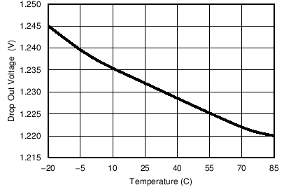
8.2.3 Application Curve

| IOUT = 50 mA |