JAJSSI7J August 2001 – December 2023 UCC29002 , UCC39002
PRODUCTION DATA
- 1
- 1特長
- 2アプリケーション
- 3概要
- 4Pin Configuration and Functions
- 5Specifications
-
6Detailed Description
- 6.1 Overview
- 6.2 Functional Block Diagram
- 6.3
Feature Description
- 6.3.1 Differential Current-Sense Amplifier (CS+, CS−, CSO)
- 6.3.2 Load-Share Bus Driver Amplifier (CSO, LS)
- 6.3.3 Load-Share Bus Receiver Amplifier (LS)
- 6.3.4 Error Amplifier (EAO)
- 6.3.5 Adjust Amplifier Output (ADJ)
- 6.3.6 Enable Function (CS+, CS−)
- 6.3.7 Fault Protection on LS Bus
- 6.3.8 Start-Up and Adjust Logic
- 6.3.9 Bias Input and Bias_OK Circuit (VDD)
- 6.4 Device Functional Modes
- 7Application and Implementation
- 8Device and Documentation Support
- 9Revision History
- Mechanical, Packaging, and Orderable Information
パッケージ・オプション
メカニカル・データ(パッケージ|ピン)
サーマルパッド・メカニカル・データ
発注情報
3 概要
UCC29002 デバイス ファミリは、高機能、高性能、低コストの負荷共有コントローラで構成されており、複数の独立した電源または DC/DC モジュールを並列接続するために必要なすべての機能を提供します。このコントローラは、サーバー、ワークステーション、テレコム、その他の分散電源システムの高信頼性アプリケーションを対象としており、既製の電源の並列接続が必要な N+1 冗長システムや大電流アプリケーションに適しています。
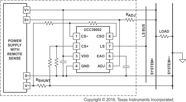
BiCMOS UCC29002 は、旧世代の UC3902 および UC3907 負荷共有コントローラの自動リーダー / フォロワ アーキテクチャをベースにしています。パッケージで調整された非常に低いオフセットの電流センス アンプと、高ゲインの負帰還ループを使用することで、全負荷時のモジュール間の電流共有誤差を 1% 以内に抑えることができます。アンプの同相範囲が VDD 電源レールまで 0V であるため、電流検出抵抗 RSHUNT は GND のリターン パス、または電源の正の出力レールのいずれかに配置できます。
パッケージ情報
| 部品番号 | パッケージ(1) | パッケージ・サイズ (公称)(2) |
|---|---|---|
| UCC29002 UCC29002-1(3) UCC39002 | SOIC (8) | 4.90mm × 6.00mm |
| UCC29002 UCC39002 | VSSOP (8) | 3.00mm × 4.90mm |
| PDIP (8) | 9.81mm × 9.43mm |
(1) 詳細は、このデータシートの末尾にある「メカニカル、パッケージ、および注文情報」セクションを参照してください。
(2) パッケージ サイズ (長さ×幅) は公称値であり、該当する場合はピンも含まれます。
(3) UCC29002-1 では、注文用型番に「/1」接尾辞を使用しています。
 代表的なローサイド電流センシング アプリケーション