DLPU049C July 2017 – October 2017 DLP2000 , DLPA1000 , DLPC2607
3 What is in the DLP LightCrafter Display 2000 EVM?
The DLP LightCrafter Display 2000 EVM consists of two subsystems:
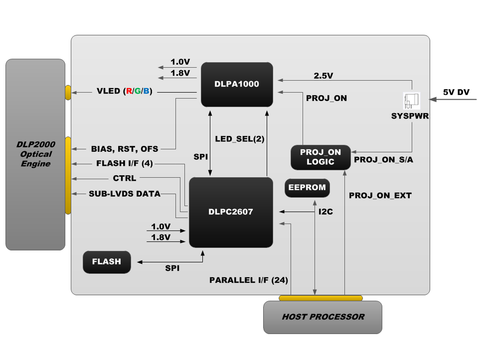
- Light engine: Includes the optics, red, green, and blue LEDs, and the 640 × 360 (nHD) DLP2000 DMD. Features a factory-default LED current drive of 320 mA (approximately 20 lumens) out of the box.
- Driver board: Includes the DLP chipset comprising of DLPC2607 display controller and DLPA1000 PMIC/LED driver. Four standoffs are provided separately to fasten this board to a BeagleBone Black.
 Figure 9. DLP LightCrafter Display 2000 EVM Block Diagram
 The light engine is held atop the driver board on a mechanical plate. The standoffs that fasten the mechanical plate to the system can be disassembled with room to attach a host processor. The system can be operated with a host processor or on its own using any I2C driver attached to the header ports P1 and P2.
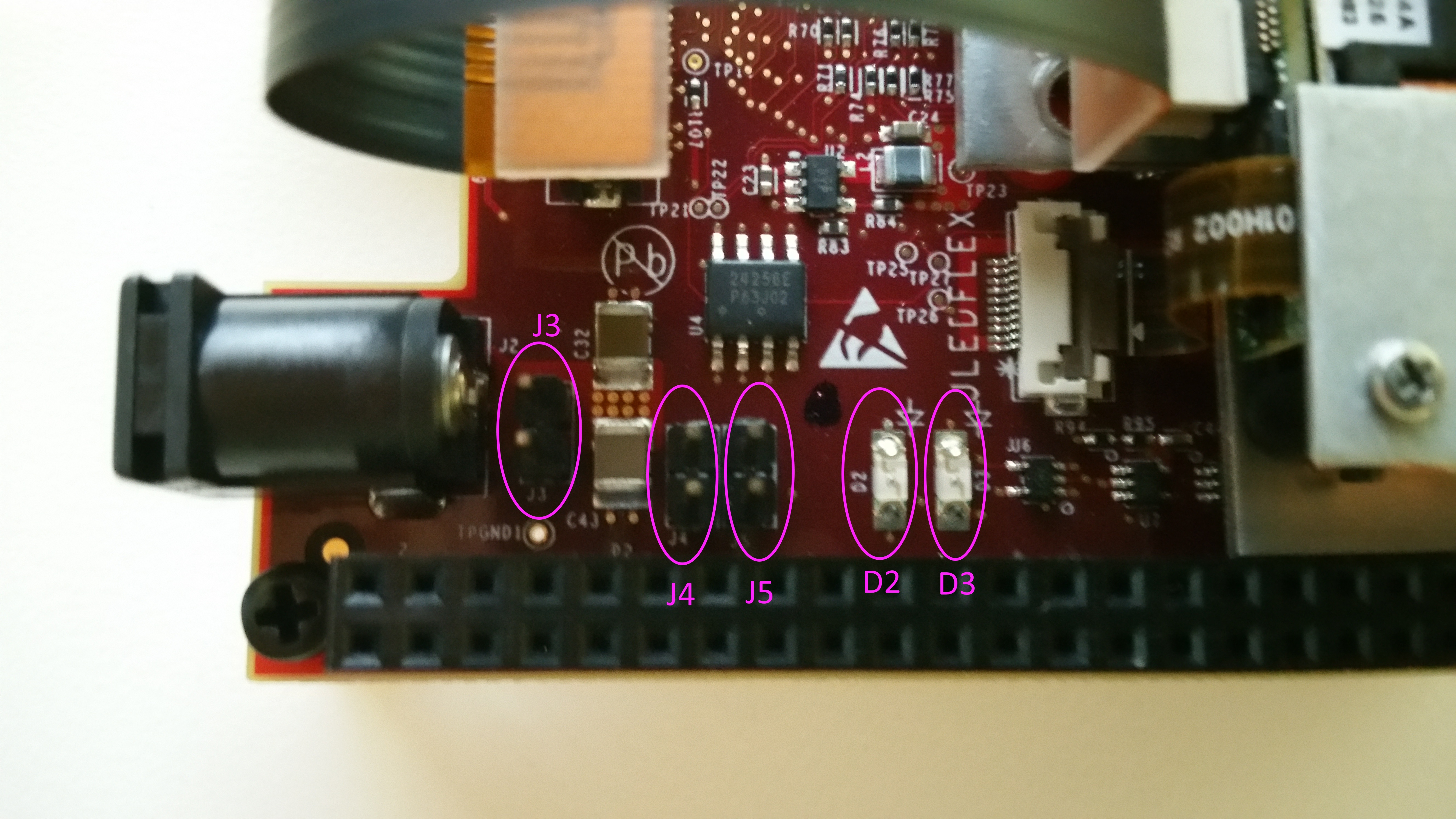
Status LEDs D2 and D3 indicate the status of HOST_IRQ and PROJ_ON respectively. HOST_IRQ will go low when the system has completed boot sequence, while PROJ_ON indicates the operational state of the EVM projector. For more information consult the DLPC2607 Data Sheet (DLPS030).
The system possesses an onboard rewritable flash memory unit which can be loaded with new firmware, as well as an onboard EEPROM. The EEPROM can be utilized with a host processor as a boot ID chip. This allows the host processor to treat the DLP LightCrafter Display 2000 EVM as a cape and automatically load appropriate device drivers on boot. The addressing configuration of this EEPROM can be managed using provided jumpers J4 (Bit 1 of address) and J5 (Bit 0 of address) located on the EVM.
 Figure 10. EVM Headers and LEDs
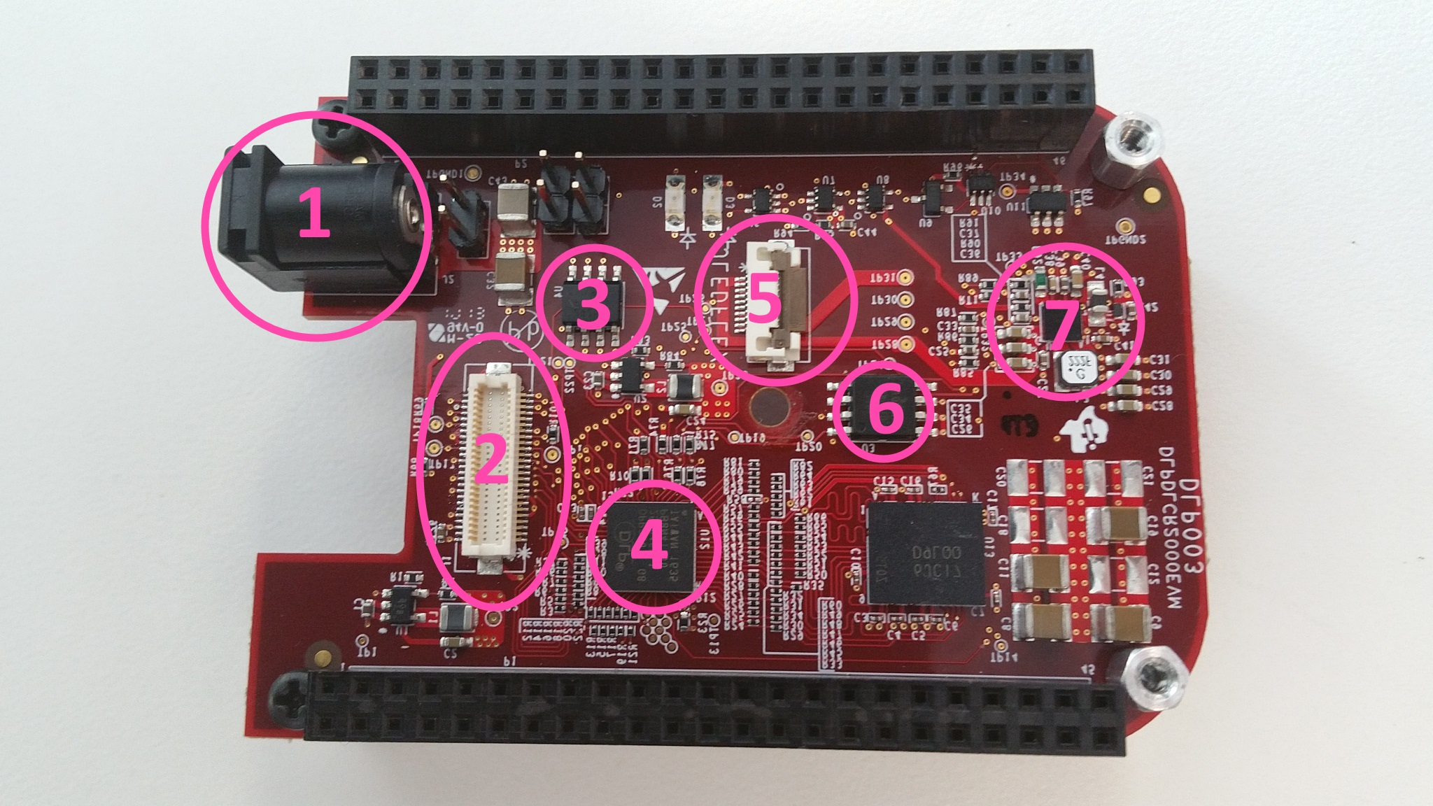
  Figure 11. DLP LightCrafter Display 2000 EVM Component Diagram
 Table 1. DLP LightCrafter Display 2000 EVM Component Chart
| ITEM NUMBER | COMPONENT |
|---|---|
| 1 | 5 V, 3 A DC Power Jack Connector |
| 2 | DMD Data Connector |
| 3 | Device ID EEPROM |
| 4 | DLPC2607 Controller |
| 5 | DMD LED Connector |
| 6 | DLPC2607 Flash Memory |
| 7 | DLPA1000 PMIC/LED Driver |