SBAA378B November 2019 – December 2023 PCM3140-Q1 , PCM5140-Q1 , PCM6140-Q1 , TLV320ADC3140 , TLV320ADC5140 , TLV320ADC6140
- 1
- Abstract
- Trademarks
- 1 Introduction
- 2 Infinite Impulse Response Filters
-
3
TLV320ADCx140/PCMx140-Q1 Digital Biquad Filters
- 3.1 Filter Design Using PurePath™ Console
- 3.2 How to Generate N0, N1, N2, D1, and D2 Coefficients with a Digital Filter Design Package
- 3.3 Avoid Overflow Conditions
- 3.4 Digital Biquad FiIter Allocation to Output Channel
- 3.5 Programmable Coefficient Registers for Digital Biquad Filters 1–6
- 3.6 Programmable Coefficient Registers for Digital Biquad Filters 7–12
- 4 How to Program the Digital Biquad Filters on TLV320ADCx140/PCMx140-Q1
- 5 Typical Audio Applications for Biquad Filtering
- 6 Crossover Networks
- 7 Voice Boost
- 8 Bass Boost
- 9 Removing 50 Hz–60 Hz Hum With Notch Filters
- 10Revision History
- 11Digital Filter Design Techniques
11.1 Analog Filters
PurePath Console Digital Filter design uses analog filter design techniques and transposes them to the digital domain. The analog filters are represented in the S-domain. Through the bilinear transformation, these analog filters are converted from the S-domain to the digital Z-domain. In these filters, each pole of the filter provides a –6 dB per octave or –10 dB per decade slope in the frequency response. Each zero of the filter provides a +6 dB per octave or +10 dB per decade slope in the frequency response. Table 11-1 shows the S-domain transfer function of the PurePath Console filter design. Note that Q = fc / Bandwidth, where fc is the center frequency.
| FILTER TYPE | TRANSFER FUNCTION | WHEN TO USE |
|---|---|---|
| Band Pass |  | Filters a set of frequencies given by bandwidth and center frequency |
| Bass Shelf | 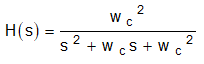 | Applies the specified gain at low frequency up to the specified cutoff frequency |
| Equalizer (Bandwidth) | 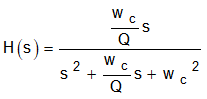 | Band-pass filter at the specified center frequency and passband width, with the specified gain |
| Equalizer (Q Factor) | Band-pass filter at the specified center frequency and quality factor, with the specified gain. The quality factor is the center frequency divided by the passband width. | |
| Gain | 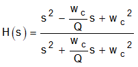 | All pass filter at the specified gain |
| High-Pass Butterworth 1 | 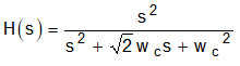 | Flat passband and stopband response with a –10 dB / decade slope past the cutoff frequency |
| High-Pass Butterworth 2 | Flat passband and stopband response with a –20 dB / decade past the cutoff frequency | |
| High-Pass Bessel 2 | 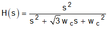 | Maximally flat magnitude and phase in passband with constant group delay at the expense of the greatest transition band |
| High-Pass Linkwitz Riley 2 |  | Use in crossover systems with the same cutoff frequency for low pass and high pass. These filters overall gain is 0 dB at the crossover point. |
| High-Pass Variable Q 2 | 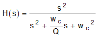 | Second-order high-pass filter at the specified center frequency, gain and quality factor. The quality factor is the center frequency divided by the passband width. |
| High-Pass Chebyshev | 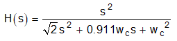 | Sharper transition band than Butterworth at the expense of ripple in the passband. |
| Low-Pass Butterworth 1 |  | Flat passband and stopband response with a –10 dB / decade slope up to the cutoff frequency |
| Low-Pass Butterworth 2 | Flat passband and stopband response with a –20 dB / decade up to the cutoff frequency | |
| Low-Pass Bessel 2 | 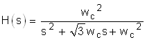 | Maximally flat magnitude and phase in passband with constant group delay at the expense of the greatest transition band |
| Low-Pass Linkwitz Riley 2 |  | Use in crossover systems with the same cutoff frequency for low pass and high pass. These filters overall gain is 0 dB at the crossover point. |
| Low-Pass Variable Q 2 | 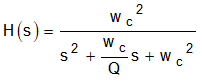 | Second-order low-pass filter at the specified center frequency, gain and quality factor. The quality factor is the center frequency divided by the passband width. |
| Low-Pass Chebyshev | 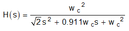 | Sharper transition band than Butterworth at the expense of ripple in the passband |
| Notch | 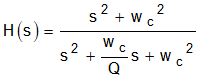 | Filter or null a specific frequency |
| Phase Shift |  | Change the phase of a signal |
| Treble Shelf | 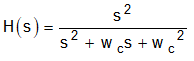 | Applies the specified gain at the high frequency past the specified cutoff frequency |