SCEA131 September 2023 TXB0101 , TXB0102 , TXB0104 , TXB0104-Q1 , TXB0106 , TXB0106-Q1 , TXB0108 , TXB0302 , TXB0304 , TXS0101 , TXS0102 , TXS0102-Q1 , TXS0104E , TXS0104E-Q1 , TXS0108E , TXS0108E-Q1
3.5 Effects of Temperature on One-Shots
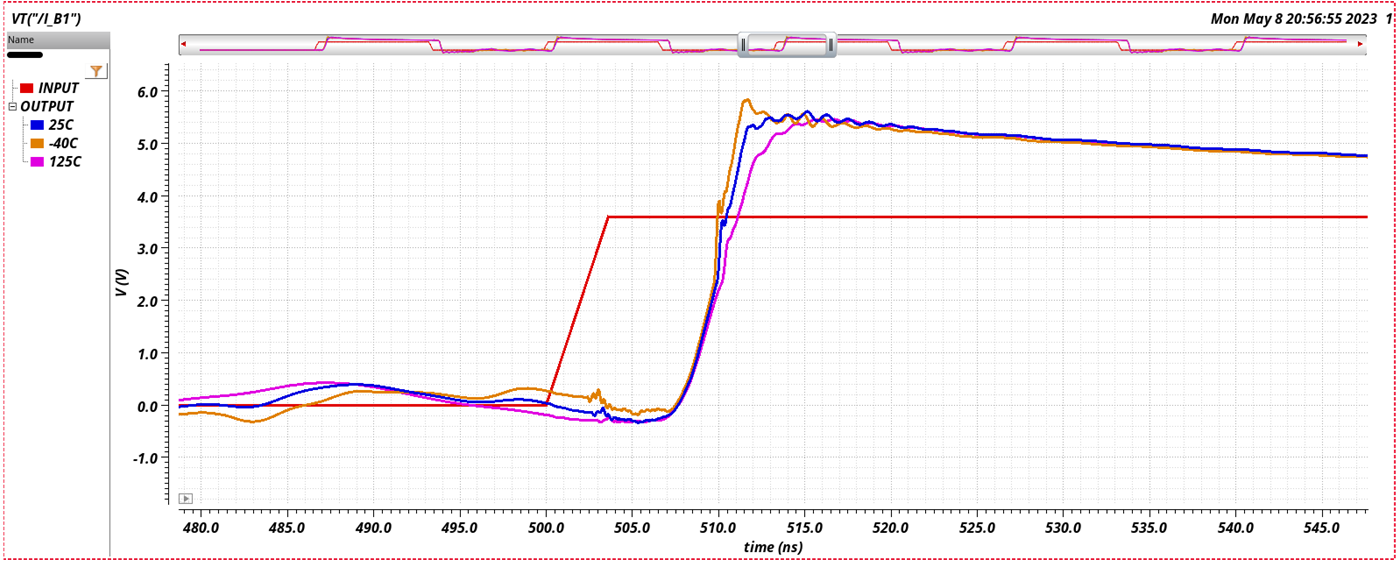
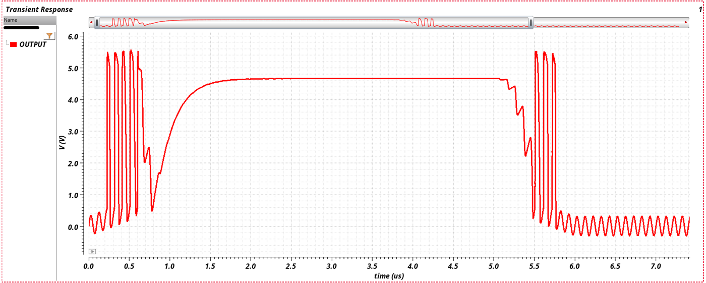
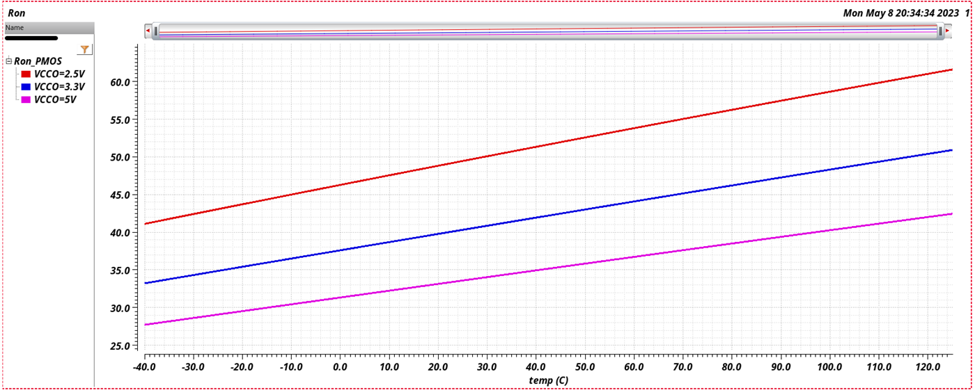
Poor design for temperature can lead to mismatched output impedance as depicted in Figure 3-13 showing how the impedance varies with temperature. We can see how the output impedance increases with temperatures. Careful consideration should be made for impedance matching to avoid amplifying the reflections. Such impedance mismatch will result in reflections which can be further amplified by the one-shot as oscillations to yield system failures similar to the Figure 3-11.
 Figure 3-10 Reflections at Cold, Room and Hot Temp
 Figure 3-11 Amplified One-shot Reflections
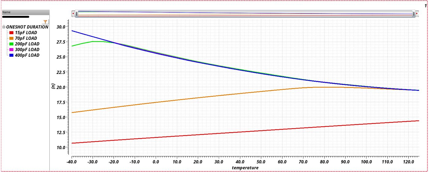
When the output impedance of the device decreases for faster data rates while the one-shot is activated, we see how key the overall output impedance is. Impedance mismatch can cause a voltage difference between the capacitance and the one-shot. If the one-shot is at an unwanted voltage, the one-shot can release the capacitance prior to being fully discharged, yielding to an expired one-shot for shorter pulse widths. Unless otherwise stated in the data sheets, note that the typical one-shot duration is designed for about 10 ns to 30 ns. Temperature and loading can significantly impact the output impedance and the one-shot duration as shown in Figure 3-14 and Figure 3-18.
 Figure 3-12 Typical Temperature Impact on Ron
 Figure 3-13 Typical Temperature Impact on Pulse Width Duration For the One-Shot
Designing for impedance matching to avoid reflections should be considered as lower temperatures yield lower impedance and higher temperatures yield higher impedance. The application’s voltage levels are also key as lower voltage nodes have the highest output impedance and higher voltage nodes have the lowest output impedance respectively, as observed with the Ron. See the device's data sheet to ensure the system is designed to accommodate the overall output impedance of the device per the system’s environment similar to the PCB layout design considerations.