SLAA600E June   2013  – January 2024


  1.   1
  2.   Abstract
  3.   Trademarks
  4. 1Introduction
    1. 1.1 Glossary
    2. 1.2 Conventions
  5. 2Implementation
    1. 2.1 Main
    2. 2.2 Application Manager
      1. 2.2.1 Boot and Application Detection
        1. 2.2.1.1 Force Bootloader Mode
        2. 2.2.1.2 Application Validation
        3. 2.2.1.3 Jump to Application
      2. 2.2.2 Vector Redirection
      3. 2.2.3 Interrupt Vectors in Flash Devices
      4. 2.2.4 Dual Image Support
        1. 2.2.4.1 Jumping to Application in Dual Image Mode
    3. 2.3 Memory Interface (MI)
      1. 2.3.1 Dual Image Support
    4. 2.4 Communication Interface (CI)
      1. 2.4.1 Physical-DataLink (PHY-DL)
        1. 2.4.1.1 I2C
          1. 2.4.1.1.1 Time-out Detection
        2. 2.4.1.2 UART
        3. 2.4.1.3 SPI
        4. 2.4.1.4 CC110x
        5. 2.4.1.5 Comm Sharing
      2. 2.4.2 NWK-APP
        1. 2.4.2.1 BSL-Based Protocol
          1. 2.4.2.1.1 Security
          2. 2.4.2.1.2 BSL-Based Protocol using CC110x
          3. 2.4.2.1.3 Examples Using I2C
          4. 2.4.2.1.4 Examples Using UART or CC110x
  6. 3Customization of MSPBoot
    1. 3.1 Predefined Customizations
  7. 4Building MSPBoot
    1. 4.1 Starting a New Project
      1. 4.1.1 Creating a New MSPBoot Project
        1. 4.1.1.1 MSPBootProjectCreator.pl
        2. 4.1.1.2 Importing Project Spec File in CCS
        3. 4.1.1.3 Modifying Generated Source Code
          1. 4.1.1.3.1 Modifying MSPBoot Main.c
          2. 4.1.1.3.2 Modifying TI_MSPBoot_Config.h
          3. 4.1.1.3.3 Modifying TI_MSPBoot_CI_PHYDL_xxxx_xxx.c
          4. 4.1.1.3.4 Modifying TI_MSPBoot_AppMgr.c
          5. 4.1.1.3.5 Modifying Application Main.c
          6. 4.1.1.3.6 Modifying TI_MSPBoot_Mgr_Vectors_xxxx.c
      2. 4.1.2 Loading Application Code With MSPBoot
        1. 4.1.2.1 Convert Application Output Images
    2. 4.2 Examples
      1. 4.2.1 LaunchPad Development Kit Hardware
      2. 4.2.2 CC110x Hardware
      3. 4.2.3 Building the Target Project
      4. 4.2.4 Building the Host Project
      5. 4.2.5 Running the Examples
  8. 5References
  9. 6Revision History

Vector Redirection

MSPBoot cannot erase or reprogram the bootloader area. This limitation provides a more secure implementation, because the bootloader is always accessible, and the MCU can be recovered by forcing bootloader mode.

The reset vector is an integral part of the bootloader, because it forces the MCU to always jump to the bootloader entry sequence, and thus it should not be erased. Because the reset vector resides in the top of 16-bit flash space (0xFFFE), the bootloader code is placed in the contiguous locations (see Figure 2-4).
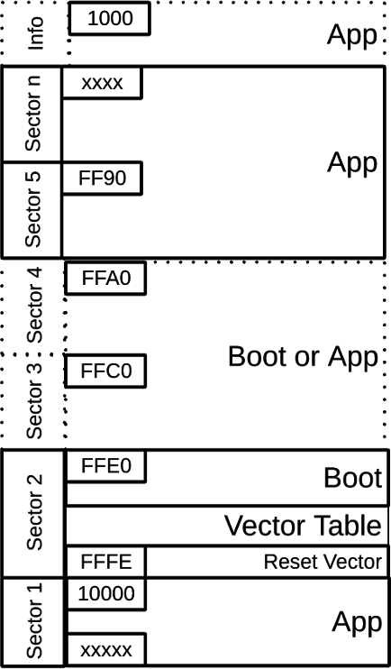
GUID-8EC1035D-E9DE-4C6C-8E93-CAD5F689F183-low.pngFigure 2-4 Memory Assignment

The interrupt vector table also resides in protected Boot area. Because the value of the interrupt table is expected to change based on the application, this means that special considerations must be followed to allow for application interrupts. Additional 20-bit space is available for the application in large memory model devices (0x10000 and above).