SLAA833A May 2018 – October 2019 MSP430FR2353 , MSP430FR2355
- How to Use the Smart Analog Combo in MSP430™ MCUs
- Revision History
4.1 Use Smart Analog Combo in Smoke Detector
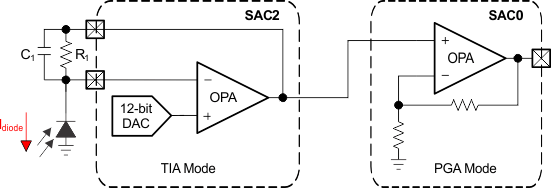
This section describes how to use SAC in real sensing and measurement applications. Smoke detector and current loop are taken as two application examples. Figure 14 shows SAC use case in smoke detector application. The first-stage SAC is configured in TIA mode, and the second-stage SAC is configured in noninverting PGA mode. The DAC is used in the first-stage SAC to provide bias voltage so the output swing limitation can be avoid. The output current of the infrared radiation (IR) receiver runs through the TIA to convert the output current of the IR receiver into an analog voltage. This analog voltage is amplified by the second-stage amplifier and then measured by the ADC on the MSP430 MCU.
The SAC supports a picoamp-level low-leakage input that improves the accuracy of current measurement. To detect currents in the range of picoamps, the feedback resistor R1 must be in the range of megaohms. Leveraging the interconnection of two SAC modules, the layout to build this kind of SAC cascading is relatively simple. The smoke detector application is constructed to minimize current consumption. The SAC modules are disabled with internal control registers when IR detection is finished. When the SAC modules are turned off, they consume no current. To improve measurement accuracy and avoid false alarms, some smoke detectors include two IR emitters with different wavelengths. The MSP430FR2355 MCU is suitable for this kind of smoke detector, as it integrates four SAC modules, which make it possible to achieve two-channel IR detection on one chip. Smoke detectors are only one of the IR sensing applications. For more details about IR sensing, see the MSP430FR2311 Microcontroller IR Reflection Sensing Reference Design.
 Figure 14. Use Smart Analog Combo in Smoke Detector