SLLA383A February 2018 – August 2022 SN65HVDA100-Q1 , SN65HVDA195-Q1 , TLIN1022-Q1 , TLIN1029-Q1 , TLIN2022-Q1 , TLIN2029-Q1 , TMS320F28P550SJ , TMS320F28P559SJ-Q1
4.3 Distance and Node Limitations
The LIN specification defines the maximum number of nodes that can be connected to a LIN bus: 1 commander node and 16 responder nodes and the max cable harness length: 40m. Because of the definitions, there is no concern about having too many nodes on the bus nor the cable being too long, opposed to other communication interfaces. Capacitance on the bus still needs to be within a reasonable range for proper communication, and this can be affected by cable length, nodes, or bus filtering.
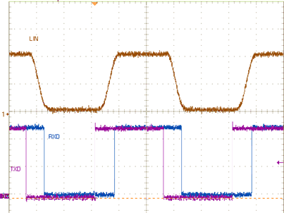
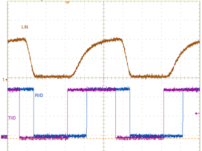
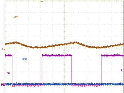
Since the cable length and node amount are limited by definition, the only parameter to keep in mind is any added capacitance; a good guideline is to stay under or close to 10-nF total bus capacitance at 20 kbps communication speed. Figure 4-1, Figure 4-2, and Figure 4-3 show the effect of having the nominal amount of capacitance, and what having too much capacitance looks like. In the case with too much capacitance, the rising edges are not able to reach the full voltage level in time for the next bit, and thus the bits are not interpreted correctly, as the RXD waveform illustrates.
 Figure 4-1 LIN Bus With 220 pF, 20 kbps Message
 Figure 4-2 LIN Bus With 10 nF, 20 kbps Message
 Figure 4-3 LIN Bus With 220 nF, 20 kbps Message