SLUAAK3 January 2024 UCC256402
- 1
- Abstract
- Trademarks
- 1Introduction
- 2UCC25640X HS Pin Has Wide dv/dt Sensing Range
- 3UCC256402/4 Eliminating the Need for the Auxpower
- 4UCC25640X has Higher Vcc Startup Voltage to Support Lower Vcc Capacitance
- 5UCC25640X has Programmable Burst Mode Threshold
- 6UCC256402A Supports Input OVP to Protect PSU if Grid Voltage is Unstable
- 7UCC25640X has Diversity Version for Each Application
- 8Summary
- 9References
3 UCC256402/4 Eliminating the Need for the Auxpower
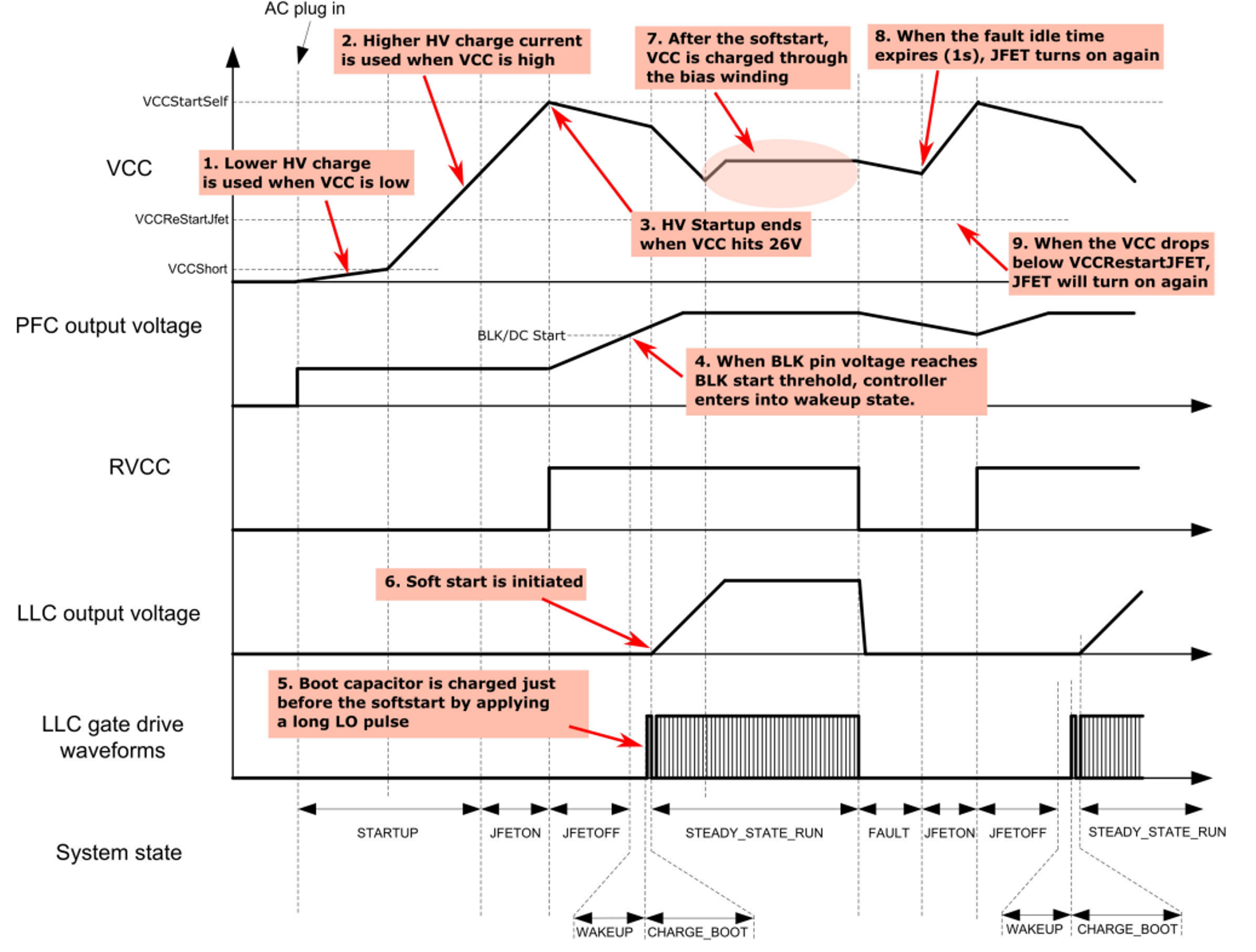
UCC256402/4 uses a self-bias start up scheme, thus eliminating the need for a separate auxiliary supply. When AC power is first plugged in, the PFC and LLC are both off. The internal JFET on the HV pin is enabled and can charge the VCC capacitor. The charge current is small when VCC pin voltage is below VCCShort and then becomes larger when VCC pin voltage is above VCCShort. Once the VCC pin voltage exceeds the VCCStartSelf threshold (26 V), the current source is turned off and RVCC is enabled to turn on the PFC. When the PFC output voltage reaches a BLK turn on threshold, then the LLC is turned on. When the LLC is operating and the output voltage is established, the bias winding can supply current for both the PFC and the LLC controller devices.
The power up sequence as Figure 3-1 showing and the UCC25640x LLC Resonant Controller Features Brief Overview and Bring up Guidelines application note introduced the UCC25640X function.
The PFC Vcc is sourced by LLC RVcc pin so LLC can turn off the PFC by disabling the RVcc when LLC triggers the protection to better protect the PFC power stage.
 Figure 3-1 Timing Diagram of System State
Machine for UCC256402 and UCC256404