SLUAAL2 june 2023 UCC256402 , UCC256403 , UCC256404
- 1
- Abstract
- Trademarks
-
1UCC25640x Frequently Asked Questions
- 1.1 For the Time Domain Simulation and Fundamental Harmonic Analysis of LLC Resonant Converters, What Model of the Transformer Should be Used?
- 1.2 How to Connect External Gate Drivers to the UCC25640x for High Gate Driver Current Capability?
- 1.3 When Powering on the PFC-LLC AC-DC Converter, What Sequence is Recommended?
- 1.4 How to Eliminate the Nuisance ZCS Detection During the Light Load?
- 1.5 What is the Purpose of Maintaining the FB Pin Voltage of the UCC25640x Controllers at a Constant Level?
- 1.6 How to Improve the Slew Rate Detection at HS Pin of the UCC25640x Controller?
- 1.7 How to Operate the UCC25640x Controller in the Open Loop?
- 1.8 What Happens if the VCR Pin Peak to Peak Voltage of the Controller Exceeds 6 V?
- 1.9 What UCC25640x settings effect the startup duration of the LLC?
- 1.10 What is Causing the Current Imbalance in the LLC's Secondary Side Windings?
- 1.11 How to Design TL431 Compensator for LLC With UCC25640x Controller
- 1.12 How to Design LLC for Battery Charging and LED Driver Applications?
- 1.13 How to Implement CC-CV Feedback Control?
- 1.14 What is the Simplest Approach to Configure the Burst Mode Thresholds for UCC25640x Based on the Load Power?
- 1.15 How to Avoid the UCC25640x Controller to Enter into Burst Mode?
- 1.16 What are the Methods for Preventing VCC From Decreasing Below the VCC Restart Threshold During Burst Mode?
- 1.17 How Does BMTL Threshold Value Impacts the Output Voltage Ripple and the VCC Pin Voltage and Magnetizing Current?
- 1.18 How to Design Magnetics for LLC?
- 1.19 How is the Dead Time in UCC25640x Determined During ZCS Detection and in the Absence of Valid Slew Rate Detection?
- 2References
1.1.1 LLC Design Using T Type Transformer Model
The reference [19] shows the LLC design using APR model whereas the reference [1] shows the LLC design using T-type transformer model. Here, for this design example, UCC25640xEVM specifications[3] with T-type transformer model is considered.
Table 1-1 UCC25640EVM-020
Specifications
| PARAMETER | TEST CONDITIONS | MIN | TYP | MAX | UNITS | |
|---|---|---|---|---|---|---|
| INPUT CHARACTERISTICS | ||||||
| DC voltage range | 365 | 390 | 410 | VDC | ||
| AC voltage range | 85 | 265 | VAC | |||
| AC voltage frequency | 47 | 63 | Hz | |||
| Input DC UVLO On | 365 | VDC | ||||
| Input DC UVLO Off | 330 | VDC | ||||
| OUTPUT CHARACTERISTICS | ||||||
| VOUT | Output voltage - Normal mode | Burst mode threshold to full load = 15 A | 12 | VDC | ||
| IOUT | Output load current | 365 to 410 VDC | 15 | A | ||
| Output voltage ripple | 390 VDC and full load = 15 A | 120 | mVpp | |||
| SYSTEM CHARACTERISTICS | ||||||
| Resonant frequency | 100 | kHz | ||||
| Peak efficiency | 390 VDC, load = 8 A | 93% | ||||
| Operating temperature | Natural convection | 25 | °C | |||
LLC Voltage Gain with T-type Transformer Model
Equation 7 gives voltage gain expression for T-type transformer model shown in Figure 1-5.
Equation 7.
where
Design Example
Equation 8.
Equation 9.
Equation 10.
Equation 11.
Equation 12.
Equation 13.
Equation 14.
Equation 15.
Equation 16.
Equation 17.
Equation 18.
Equation 19.
Equation 20.
Equation 21.
Equation 22.
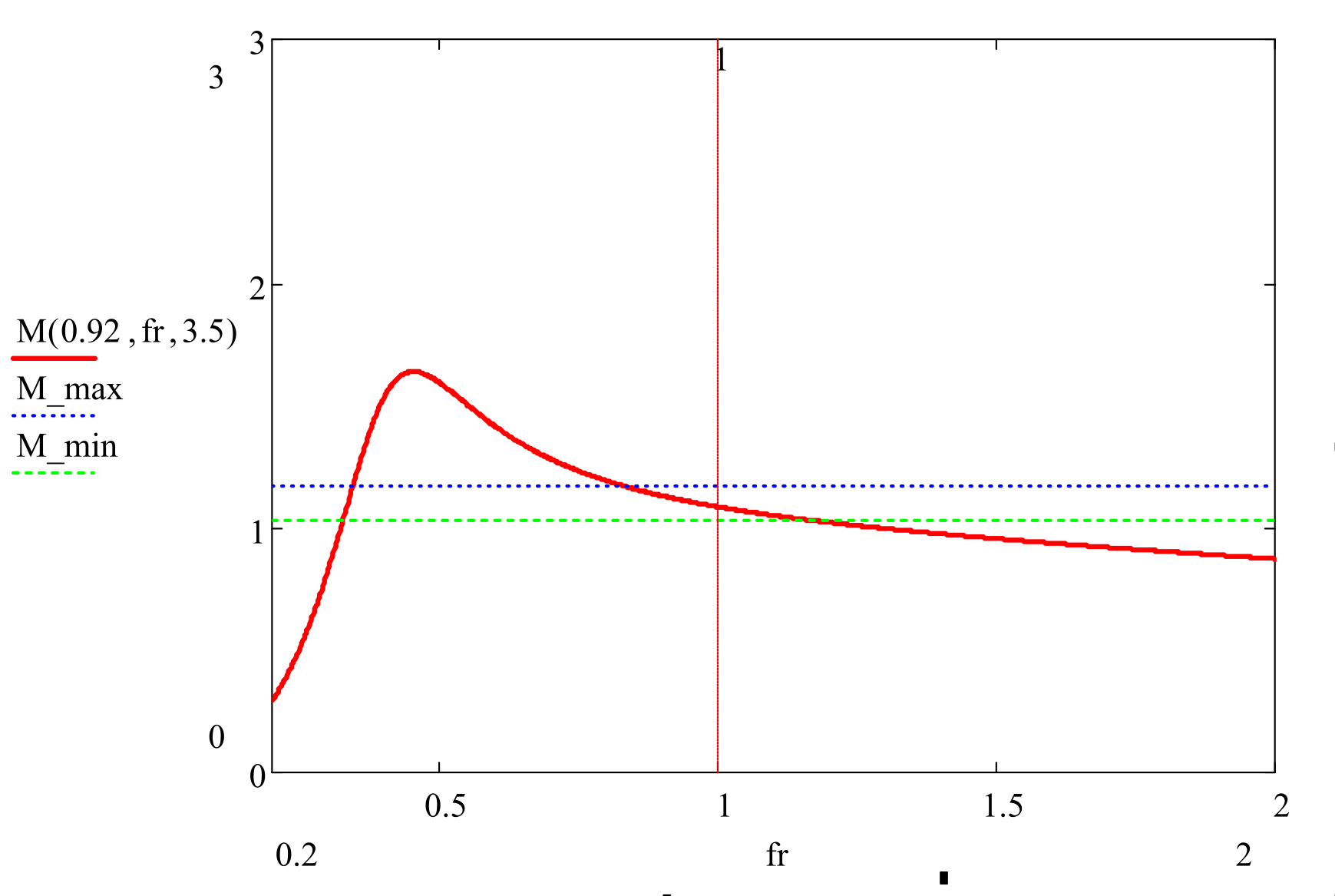
 Figure 1-8 Gain Frequency Plot for k=0.92
and Q=3.5
Figure 1-8 Gain Frequency Plot for k=0.92
and Q=3.5Equation 23.
Equation 24.
Equation 25.
Equation 26.
Equation 27.
Equation 28.
Equation 29.
Equation 30.